Thermal: Difference between revisions
(→SB) |
(Hmmm, it seems all the "local" temperaure monitors (SB, BEVR, EEGS) allows to configure his "I2C address" by pulling up/down the pins A0, A1, A2) |
||
| Line 269: | Line 269: | ||
| 2 || SCL || from THR_I2C_SCL (via R7074 {{unk|50{{Ohm}}}}) | | 2 || SCL || from THR_I2C_SCL (via R7074 {{unk|50{{Ohm}}}}) | ||
|- | |- | ||
| 3 || OTI || | | 3 || OTI || Not connected | ||
|- | |- | ||
| 4 || GND || Ground | | 4 || GND || to Ground | ||
|- | |- | ||
| 5 || A2 || to Ground | | 5 || A2 || to Ground | ||
|- | |- | ||
| 6 || A1 || to | | 6 || A1 || from '''[[Regulators#OnSemi_NCP511SN33T1G_.283.3V_150_mA_CMOS_Low_Iq_Low-Dropout_Voltage_Regulator.29|+3.3V_THERMAL]]''' (with C7286 0.1{{micro}}F B 10V 1005 to ground as filter) | ||
|- | |- | ||
| 7 || A0 || to | | 7 || A0 || to Ground | ||
|- | |- | ||
| 8 || VDD || from '''[[Regulators#OnSemi_NCP511SN33T1G_.283.3V_150_mA_CMOS_Low_Iq_Low-Dropout_Voltage_Regulator.29|+3.3V_THERMAL]]''' (with C7286 0.1{{micro}}F B 10V 1005 to ground as filter) | | 8 || VDD || from '''[[Regulators#OnSemi_NCP511SN33T1G_.283.3V_150_mA_CMOS_Low_Iq_Low-Dropout_Voltage_Regulator.29|+3.3V_THERMAL]]''' (with C7286 0.1{{micro}}F B 10V 1005 to ground as filter) | ||
Revision as of 08:40, 29 January 2022
Relative: see also Cooling, Thermal, Syscon Thermal Configs
Motherboard Thermal Management
All the thermal sensors of the PS3 motherboard are connected to syscon, the current temperatures are compared with the settings of a syscon EEPROM region named thermal config and based in the results of the comparison syscon sets a fan speed
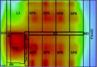
CELL BE Internal Powermanagement
- Dynamic Power Managment with 5 power managment states
- 1 linear sensor (diode)
- 10 digital thermal sensors (8xSPE, PPE and ?)
RSX internal Powermanagement
- 1 linear sensor (diode)
- Internal selfmanagement: Unknown
Temperature Monitors
The internal circuitry of CELL, RSX, and other components of the PS3 motherboard contains temperature sensors (also known as diodes) that outputs an analog signal throught 2 lines (named D+ and D-), this signal is taken by a dedicated chip named "temperature monitor" that converts it to digital (bytes)
The connection in between syscon and the thermal monitors is made by a protocol named SMBus with 2 lines named SCL (serial clock) and SDA (serial data). Syscon is the master of the SMBus and the thermal monitors are the slaves connected in cascade to the same 2 lines of the SMBus. Syscon generates the SCL clock signal (the clock is an output of syscon, and a input for the monitors), and the SDA data signal is bidirectional
SMBus protocol is based on the I2C protocol, there are some differences but a lot more things in common, all the slaves connected to the SMBus have a unique address given by the manufacturer of the component (and cant be changed, this is why each thermal monitor of the PS3 motherboard have a different component name (as example TMP411A for CELL and TMP411B for RSX)
The SMBus lines are protected in internal layers of the motherboard between 2 ground layers to shield them against interferences
- See also:
- Texas Instruments TMP411 Product page
- Onsemi ADT7461 Product page and Onsemi ADT7461A Product page (design previously property of Analog Devices Inc.)
- Analog Devices Product Line Sold to Onsemi (December 31, 2007)
- Analog Devices ADT7461 ±1°C Temperature Monitor with Series Resistance Cancellation (2003 Rev 0)
- Analog Devices ADT7461* ±1°C Temperature Monitor with Series Resistance Cancellation (2005 Rev B)
- Onsemi ADT7461 ±1°C Temperature Monitor with Series Resistance Cancellation.PDF (March 2014 - Rev.8)
- Onsemi ADT7461A ±1°C Temperature Monitor with Series Resistance Cancellation.PDF (April, 2013 − Rev. 8)
| Mother Board | CELL | RSX | SB | EEGS | BEVR | GbE | XDR | Air intake | Others/Notes |
|---|---|---|---|---|---|---|---|---|---|
| TMU-520 | ADT7467 | ADT7467 | ADT75 | N/A | N/A | ADT75 | ADT75 | ADT75 | |
| Thermal Config format 1 Mullion old | |||||||||
| COK-001 | AD51 | T1L | AD51 | AD51 ? | AD51 ? | N/A | N/A | N/A | |
| COK-002 | AD51 | T1L | AD51 | AD51 ? | AD51 ? | N/A | N/A | N/A | |
| Thermal Config format 2 Mullion new | |||||||||
| SEM-001 | AD51 | T1L | AD51 | N/A | N/A | N/A | N/A | N/A | |
| DIA-001 | T1B or 411A | T1L or 411B | AD51 ? | N/A | N/A | N/A | N/A | N/A | |
| DIA-002 | T1B | T1L | AD51 ? | N/A | N/A | N/A | N/A | N/A | Speculation: either onsemi T1B/T1L or texas instruments 411A/411B |
| DEB-001 | ? | ? | AD51 ? | N/A | N/A | N/A | N/A | N/A | Speculation: either onsemi T1B/T1L or texas instruments 411A/411B |
| Thermal Config format 3 Sherwood | |||||||||
| VER-001 | 411A | 411B | N/A | N/A | N/A | N/A | N/A | N/A | Speculation: either onsemi T1B/T1L or texas instruments 411A/411B |
| DYN-001 | T1B or 411A | T1L or 411B | N/A | N/A | N/A | N/A | N/A | N/A | |
| SUR-001 | 411A | 411B | N/A | N/A | N/A | N/A | N/A | N/A | |
| JTP-001 | 411A | 411B | N/A | N/A | N/A | N/A | N/A | N/A | |
| JSD-001 | 411A | 411B | N/A | N/A | N/A | N/A | N/A | N/A | |
| KTE-001 | 411A | 411B | N/A | N/A | N/A | N/A | N/A | N/A | |
| MSX-001 | 411A | 411B | N/A | N/A | N/A | N/A | N/A | N/A | |
| MPX-001 | 411A | 411B | N/A | N/A | N/A | N/A | N/A | N/A | |
| NPX-001 | 411A | 411B | N/A | N/A | N/A | N/A | N/A | N/A | |
| PPX-001 | ? | ? | N/A | N/A | N/A | N/A | N/A | N/A | |
| PQX-001 | 411A | 411B | N/A | N/A | N/A | N/A | N/A | N/A | |
| RTX-001 | ? | ? | N/A | N/A | N/A | N/A | N/A | N/A | |
| REX-001 | 411A | 411B or 201BI1309L | N/A | N/A | N/A | N/A | N/A | N/A | |
It seems in COK-001 (and probably all pre-retail motherboards) the company "analog devices" was supplying the temperature monitors to sony, can be identifyed by the triangle logo of the company next to the branding code T1B and T1L. Around december 2008 "analog devices" sold the patent to "onsemi" and they removed the triangle logo, as a consequence the temperature monitors of the COK-002 (and/or newer made by onsemi) doesnt have the triangle logo but are still branded as "T1B" and "T1L". Around DIA-001 motherboard sony started working with texas instrument as the supplyers of the temperature monitors, seems to be fully compatibles with the previous ones and this PS3 motherboards (up to DYN-001 or so) was shipped with any of them (either onsemi or texas instrument)
CELL (1st BE Primary)
AD51/067ARMZ-REEL (2 channel Thermal Monitor SMbus IC)
6-710-287-01 / IC1101 (in CECHAxx, CECHBxx, CECHCxx, CECHExx)
IC1002 (in CECHGxx)
Used for monitoring the CELL BE
- I2C address = 100 1100 (0x4C)
| Pin | Signal | Description |
|---|---|---|
| 1 | VDD | from +3.3V_THERMAL (with C1104 0.1μF B 10V 1005 to Ground as filter) |
| 2 | D+ | from CELL BE AU17 pad STI_THERMAL0 via R1106 100 Ohm and C1103 0.001μF 50V |
| 3 | D- | from CELL BE AT17 pad STI_THERMAL1 via R1107 100 Ohm and C1103 0.001μF 50V |
| 4 | /THERM | |
| 5 | GND | Ground |
| 6 | /THERM2 | to /THRBE_SENS_ALRT |
| 7 | SDATA | from THR_I2C_SDA |
| 8 | SCLK | from THR_I2C_SCL |
- In JSD-001
- Texas Instrument Remote Junction Temperature Sensor TMP411A
- pin 1 (VDD) connected to pin 8 of voltage regulator 463A (3.3v standby named 3.3_EVER_A)
- pin 4 connected to CELL ?
- pin 6 not connected
- pin 7 (THR_I2C_SDA) connected to syscon SWx-x series pin 24 by a 50ohm resistor
- pin 8 (THR_I2C_SCL) connected to syscon SWx-x series pin 25
RSX (RSX Primary)
OnSemi ADT7461A (2 channel Thermal Monitor SMbus IC CELL BE/RSX)
6-710-286-01 / IC2101
Used for monitoring the RSX
- I2C address = 100 1101 (0x4D)
| Pin | Signal | Description |
|---|---|---|
| 1 | VCC | from +3.3V_THERMAL (with C2108 0.1μF B 10V 1005 to Ground as filter) |
| 2 | D+ | from RSX AW12 pad RSX_TDP via R2101 100 Ohm and C2103 0.001μF 50V |
| 3 | D- | from RSX AY12 pad RSX_TDN via R2102 100 Ohm and C2103 0.001μF 50V |
| 4 | /THERM | to RSX AV14 pad RSX_GPIO6 / RSX_THR_EVENT |
| 5 | GND | Ground |
| 6 | /THERM2 | to /THRRSX_SENS_ALRT |
| 7 | SDATA | from THR_I2C_SDA |
| 8 | SCLK | from THR_I2C_SCL |
- In JSD-001
- Texas Instrument Remote Junction Temperature Sensor TMP411B
- pin 1 (VDD) connected to pin 8 of voltage regulator 463A (3.3v standby named 3.3_EVER_A)
- pin 4 connected to RSX
- pin 6 not connected
- pin 7 (THR_I2C_SDA) connected to syscon SWx-x series pin 24 by a 50ohm resistor
- pin 8 (THR_I2C_SCL) connected to syscon SWx-x series pin 25
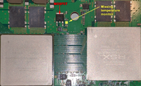
BE VR
AD51/007Z-0REEL
IC6108 on COK-001 (unpopulated). Used for monitoring the VOLTAGE REGULATOR IC6303 BD3520FVM-TR and the MOSFET Q6310 SUD40N02-08-E3 that generates +1.2V_YC_RC_VDDIO for CELL
Configured as "local"
| Pin | Signal | Description |
|---|---|---|
| 1 | SDA | from THR_I2C_SDA |
| 2 | SCL | from THR_I2C_SCL |
| 3 | OTI | Not connected |
| 4 | GND | to Ground |
| 5 | A2 | to Ground |
| 6 | A1 | to Ground |
| 7 | A0 | to Ground |
| 8 | VDD | from +3.3V_THERMAL (with C6168 0.1μF B 10V 1005 to ground as filter) |
SB
AD51/007Z-0REEL
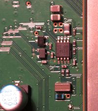
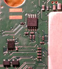
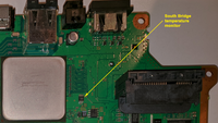
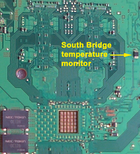
6-710-196-01 / IC3101 (on CECHAxx CECHBxx CECHCxx CECHExx). Located in between SB and the SATA connector. Configured as "local"
IC3002 (on CECHGxx). Located at the bottom (and a bit far away) from the South Bridge
Used for monitoring the South Bridge
| Pin | Signal | Description |
|---|---|---|
| 1 | SDA | from THR_I2C_SDA |
| 2 | SCL | from THR_I2C_SCL |
| 3 | OTI | Not connected |
| 4 | GND | to Ground |
| 5 | A2 | to Ground |
| 6 | A1 | to Ground |
| 7 | A0 | from +3.3V_THERMAL (with C3155 0.1μF B 10V 1005 to ground as filter) |
| 8 | VDD | from +3.3V_THERMAL (with C3155 0.1μF B 10V 1005 to ground as filter) |
EE+GS
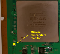
IC7005 on COK-001 motherboard (unpopulated), located next to the pad 1 corner of EE+GS. Configured as "local"
AD51/007Z-0REEL
Used for monitoring the CXD9833GB
| Pin | Signal | Description |
|---|---|---|
| 1 | SDA | from THR_I2C_SDA (via R7073 ?50Ω?) |
| 2 | SCL | from THR_I2C_SCL (via R7074 ?50Ω?) |
| 3 | OTI | Not connected |
| 4 | GND | to Ground |
| 5 | A2 | to Ground |
| 6 | A1 | from +3.3V_THERMAL (with C7286 0.1μF B 10V 1005 to ground as filter) |
| 7 | A0 | to Ground |
| 8 | VDD | from +3.3V_THERMAL (with C7286 0.1μF B 10V 1005 to ground as filter) |
Temperature Monitors Configuration
The temperature monitors allows to be configured in many ways by modifying some registers (see datasheets), this configurations are specific for the PS3 motherboard design and is unknown if is stored in a "non-volatile way" inside the temperature monitors or if is syscon who configures them everytime the PS3 motherboard is powered as part of syscon initialization procedures
The SMBus in between syscon and the thermal monitors is a digital channel, we can consider all this configuration and 100% of the data transfered in the SMBus channel as bytes, and in theory it should be insensitive to intereferences or innacuracies
Local VS Remote sensor
The temperature monitors contains a sensor integrated inside them and are able to meassure another external sensor, this modes are named "local sensor" and "remote sensor". In local mode the temperature monitor is meassuring the temperature of itself (and indirectly the surrounding components), in remote mode are meassuring the temperature of another component
In COK-001 the temperature monitors for CELL and RSX are configured as remote (meassures the sensors inside CELL and RSX cores), but the others for SB, EEGS, BEVR are intended to be configured as local
Temperature Data Format
- The temperature monitors of all PS3 models have the temperature data format (high/first byte) configured as Standard range. To cover a range of 0ºC up to 127ºC. All temperatures lower or equal than 0ºC are represented with 0x00 and all temperatures higher or equal than 127ºC are represented with 0x7F
- The temperature data is managed with 2 bytes, the high/first byte represents the celsius degress as a integer value, eg: 1, 37, 101, etc... And the low/second byte represents a fraction of a celsius degree, eg: 0.5, 0.75, 0.0625 etc...
- The high/first byte can be converted to celsius degress by a direct decimal conversion, eg: 0xA=10ºC
- The low/second byte can be converted from the hex value to a fraction of 1 celsius degre with the formula (decimal*100)/256. And the resulting value will be rounded following the tables below, eg 0x80 = (128*100)/256 = 50 (half a celsius degree, in other words 0.5ºC). This rounding depends of how is configured the "resolution" of the low/second byte and varyes per PS3 model
- Inside the Syscon Thermal Configs the temperature values for "TempU" and "TempD" are in little endian for Sherwood, and big endian for Mullion. The other temperatures ("trp", "tshutdown" and "hyst") are in big endian for all syscon models
- The temperature monitors of COK-001 motherboard have the temperature data format (low/second byte) configured to use a 0.0625°C resolution, eg: the highest temperature that can be represented is 127.9375ºC with the bytes 0x7F 0xF0
- The temperature monitors of DYN-001 motherboard have the temperature data format (low/second byte) configured to use a 0.25°C resolution, eg: the highest temperature that can be represented is 127.75ºC with the bytes 0x7F 0xC0
- However, all the temperature values found in all the official thermal configs are adjusted to a 0.5ºC resolution
| Temperature (integer) |
Range | |
|---|---|---|
| Extended | Standard | |
| -64ºC | 0x00 | 0x00 |
| -63ºC | 0x01 | |
| Etc... | Etc... | |
| -1ºC | 0x3F | |
| 0ºC | 0x40 | |
| 1ºC | 0x41 | 0x01 |
| 2ºC | 0x42 | 0x02 |
| Etc... | Etc... | Etc... |
| 125ºC | 0xBD | 0x7D |
| 126ºC | 0xBE | 0x7E |
| 127ºC | 0xBF | 0x7F |
| 128ºC | 0xC0 | |
| Etc... | Etc... | |
| 190ºC | 0xFE | |
| 191ºC | 0xFF | |
| Temperature (decimal) |
Resolution | |||
|---|---|---|---|---|
| 0.0625°C | 0.125°C | 0.25°C | 0.5°C | |
| 0.0000ºC | 0x00 | 0x00 | 0x00 | 0x00 |
| 0.0625ºC | 0x10 | |||
| 0.1250ºC | 0x20 | 0x20 | ||
| 0.1875ºC | 0x30 | |||
| 0.2500ºC | 0x40 | 0x40 | 0x40 | |
| 0.3125ºC | 0x50 | |||
| 0.3750ºC | 0x60 | 0x60 | ||
| 0.4375ºC | 0x70 | |||
| 0.5000ºC | 0x80 | 0x80 | 0x80 | 0x80 |
| 0.5625ºC | 0x90 | |||
| 0.6250ºC | 0xA0 | 0xA0 | ||
| 0.6875ºC | 0xB0 | |||
| 0.7500ºC | 0xC0 | 0xC0 | 0xC0 | |
| 0.8125ºC | 0xD0 | |||
| 0.8750ºC | 0xE0 | 0xE0 | ||
| 0.9375ºC | 0xF0 | |||
Readout of Thermal and Fan data using Software
Readable in software with Sycalls: sys_game_get_temperature (sc383), sys_sm_get_tzpb (sc384), sys_sm_get_fan_policy (sc409)
Fan settings per PS3 model based on syscon data reads
| PS3 Model | MotherBoard | Syscon | Heatsink (Fan Ø) | Fan Steps | Overheat Shutdown Temperature |
Fantest mode Supported | ||||||||||||||||||||||||||||||||||
|---|---|---|---|---|---|---|---|---|---|---|---|---|---|---|---|---|---|---|---|---|---|---|---|---|---|---|---|---|---|---|---|---|---|---|---|---|---|---|---|---|
| Step 1 | Warmup | Step 2 | Step 3 | Step 4 | Step 5 | Step 6 | Step 7 | Step 8 | Step 9 | Step 10 | Step 11 | Step 12 | ||||||||||||||||||||||||||||
| Temp1 | Speed1 | Temp2 | Speed2 | Temp3 | Speed3 | Temp4 | Speed4 | Temp5 | Speed5 | Temp6 | Speed6 | Temp7 | Speed7 | Temp8 | Speed8 | Temp9 | Speed9 | Temp10 | Speed10 | Temp11 | Speed11 | Temp12 | Speed12 | |||||||||||||||||
| CECHAxx | COK-001 | CXR713 Series | Type_1 (14 cm) | No | ||||||||||||||||||||||||||||||||||||
| CECHBxx | COK-001 | CXR713 Series | Type_1 (14 cm) | No | ||||||||||||||||||||||||||||||||||||
| CECHCxx | COK-002 | CXR713 Series | Type_1 (14 cm) | 20/20 | 0x33 (20%) | 72/65 | 0x40 (25%) | 74/66 | 0x48 (28%) | 75/66 | 0x4D (31%) | 76/68 | 0x55 (35%) | No more fan steps ? | No more fan steps ? | No more fan steps ? | No more fan steps ? | No more fan steps ? | No more fan steps ? | No more fan steps ? | No | |||||||||||||||||||
| CECHExx | COK-002 | CXR713 Series | Type_1 (14 cm) | No | ||||||||||||||||||||||||||||||||||||
| CECHGxx | SEM-001 | CXR713 Series | Type_2 (14 cm) ? | Yes | ||||||||||||||||||||||||||||||||||||
| CECHHxx | DIA-001 | CXR714 Series | Type_3 (14 cm) ? | Yes | ||||||||||||||||||||||||||||||||||||
| CECHJxx | DIA-002 | CXR714 Series | Type_3 (14 cm) ? | Yes | ||||||||||||||||||||||||||||||||||||
| CECHKxx | DIA-002 | CXR714 Series | Type_3 (14 cm) ? | Yes | ||||||||||||||||||||||||||||||||||||
| CECHLxx | VER-001 | SW Series | Type_4 (14 cm) ? | Yes | ||||||||||||||||||||||||||||||||||||
| CECHMxx | VER-001 | SW Series | Type_4 (14 cm) ? | Yes | ||||||||||||||||||||||||||||||||||||
| CECHPxx | VER-001 | SW Series | Type_4 (14 cm) ? | Yes | ||||||||||||||||||||||||||||||||||||
| CECHQxx | VER-001 | SW Series | Type_4 (14 cm) ? | Yes | ||||||||||||||||||||||||||||||||||||
| CECH-20xx | DYN-001 | SW2 Series | Type_5 (10 cm) | 20/20 | 0x33 (20%) | 53/45 | 0x39 (22%) | 54/46 | 0x3B (23%) | 55/47 | 0x3E (24%) | 56/47 | 0x40 (25%) | 57/48 | 0x43 (26%) | 60/62 | 0x45 (27%) | 65/66 | 0x48 (28%) | 69/71 | 0x4A (29%) | Unknown fan steps | Unknown fan steps | Unknown fan steps | Yes | |||||||||||||||
| CECH-21xx | SUR-001 | SW2 Series | Type_5 (10 cm) | Yes | ||||||||||||||||||||||||||||||||||||
| CECH-25xx | JTP-001 | SW2 Series | Type_5 (10 cm) | 20/20 | 0x33 (20%) | 58/54 | 0x39 (22%) | 59/57 | 0x3B (23%) | 60/60 | 0x3E (24%) | 62/61 | 0x40 (25%) | 63/62 | 0x43 (26%) | 64/64 | 0x45 (27%) | 65/65 | 0x48 (28%) | 70/69 | 0x4A (29%) | 73/73 | 0x50 (31%) | Unknown fan steps | Unknown fan steps | ??/?? | Yes | |||||||||||||
| CECH-25xx | JSD-001 | SW2 Series | Type_5 (10 cm) | 20/20 | 0x33 (20%) | 59/54 | 0x39 (22%) | 60/56 | 0x3B (23%) | 60/59 | 0x3E (24%) | 61/59 | 0x40 (25%) | 62/61 | 0x43 (26%) | 64/65 | 0x45 (27%) | 65/66 | 0x48 (28%) | 69/70 | 0x4A (29%) | Unknown fan steps | Unknown fan steps | Unknown fan steps | ??/?? | Yes | ||||||||||||||
- Notes
- The table uses an ambient temperature of 20 celsius degrees, the value doesnt matters for the purpose of the table. PS3 manual states: Ambient Operating temperature 5°C - 35°C (41°F - 95°F)
- In "Temp1" column the exact temperature has no importance, there is a big gap in this first step (from minimal to around 54º the fan speed is the same), but the fan speed associated in "Speed1" is needed to know because is the minimal
- Temperatures in the format XX/YY are CELL/RSX in celsius degrees (°, {{degree}}, {{°}} or °)
- Fan speeds are in hexadecimal and in percentages
- Firmware installations can change fan configuration values in syscon so the values can vary depending of firmware
- Fan has a special "test/clean" mode that sets the fan at max speed, only works in some PS3 models, to enter this mode first disconnect power cord from the wallet, then press eject button and keep it pressed, then connect power cord to the wallet
- When the temperature of the PS3 is decreasing (like when exiting a game) it takes around 2 minutes to step back to the previous speed (to dont disturb the user with too much speed changes up and down). And never returns to the initial speed of 0x33 (tested for 20 minutes)
To make this test, first install "iris manager" and configure the fan speeds to be controlled by syscon (sys_sm_get_fan_policy in mode 1 allows to see the default values syscon is using in real time at the bottom of the screen)... then turn off the PS3 and let it cool for some hours to return to ambient temperature
After this preparation start the test by turning on the PS3 and enter in iris, go to fancontrol settings screen as faster as possible, then start taking notes of how the values that appears at the bottom of the screen changes over time
This test can last over 60 minutes in some PS3 models and will not reach the higher temperature values because the efficiency of the cooling system doesnt allows the PS3 to overheat for obvious reasons. The maximun temperature on the test is not important for this table, the values of the fan speeds are (and the temperature asociated with this fan speed change)
A controlled overheat can be forced by blocking the airflow grills (any of them) with a plastic bag, only use this method for small overheats around 4º or 5º that are the normal peaks that will be present in-game. When manual overheating never exceed the overheat shutdown temperature that is around 85º because this can cause a permanent damage to the motherboardHomebrew for thermal and fan read and control
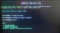
- control_fan_utility_v0.3.rar (including source) mirror for 4.31 and 4.40 // original thread
- control_fan_utility_v1.0.rar (including source) mirror for 3.41, 3.55, 4.21, 4.30 and 4.40 // original thread
- control_fan_utility_v1.6.rar (added support for Remote Play) mirror // original thread
- control_fan_utility_v1.7.rar (added support for more firmwares) // original thread
- Control Fan Utility 1.8.1 (unofficial mod by Alexander)
- Fan Control Utility v1.9: Now Supports ALL 4.46 CFW // D/L (unofficial mod by Alexander)
- irismanager-4-x.rar (with fancontrol/thermal output) // original thread
Default values used by the payload included in "control fan utility" and "iris manager"
| # | value | mode | notes |
|---|---|---|---|
| 0 | 0x5f | sm_shutdown / manual mode | |
| 1 | 0x4d | < temp_control0 | |
| 2 | 0x54 | temp_control0 => temp_control1 | |
| 3 | 0x60 | temp_control0 <= temp_control1 | |
| 4 | 0x68 | >= temp_control1 | |
| 5 | 0x70 | >= temp_control2 | |
| 6 | 0x78 | >= temp_control3 | |
| 7 | 0xA0 | >= temp_control4 |
| # | temp | note |
|---|---|---|
| 0 | 62 | |
| 1 | 68 | |
| 2 | 70 | |
| 3 | 72 | |
| 4 | 75 |
using TC and ccapi
prerequisites:
- A PS3 in CFW and connected to the LAN.
- A PC connected to the local network.
- The PKG and the following plugin : http://www.mediafire.com/download/lec46ljzazooaqr/CcApi_2.00_package.rar
- The PC tool Temp Control 1.0 that you can find by following this link : http://www.mediafire.com/download/8hypjcxsj8lpq3j/TC101.zip
- NET Framework 4.5 installed on your PC (you can get it in the following link) : http://www.microsoft.com/en-us/download/details.aspx?id=30653
Step by step:
- Unzip the package 'CcApi_2.00_package.rar' on your pc and copy the folder 'plugins' to the root of your external hard drive or USB flash drive.
- Copy 'XX0001-ENSTONEXX_00-00000000000CCAPIv2.00.pkg' also to the root of your external hard drive or USB
- Now go to the ps3, and install the pkg 'XX0001-ENSTONEXX_00-00000000000CCAPIv2.00.pkg', then reboot when it is demanded.
- When your PS3 restarts, a popup will appear at the launch of the xmb telling you that the plugin has successfully been loaded.
- Now go to the PC, unzip the package 'TC101.zip' and run 'Temp Control.exe'.
- Enter the IP address of the PS3 in the red zone.
- Then click 'connect' in Blue.
- The temperatures will be displayed in green.
- Check the box PS3 notifications and temperatures will consistently be displayed on the TV screen.
Using this will allow you to see the actual temperature of the ps3 and to be aware when the temperature goes very high so you turn it off and avoid a problem of your ps3 system.
source: http://wololo.net/talk/viewtopic.php?f=67&t=38795
Thermal Images
90nm / 60GB FAT and 65nm / 40GB FAT
These tests aren't by any means scientific, as we only heated the PS3's with the "Folding @ Home" application included with "Life With PlayStation" for about an hour, as the temperature had reached it's peak by then. The findings may surprise some of you, as earlier reports stated the 40GB PS3's used much less power and emitted less heat as a result of a smaller CELL processor and some other differences.
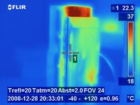
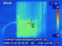
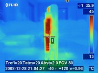
| With the ambient temperature at about 22 Celcius, we started taking pictures. As you can see in the first image below, the upper-right part of the PS3 heats up the fastest, because this is where the ventilation system outputs most of the hot air building up inside of the console. Already in this image, you can see the power supply in the lower right corner heating up. |
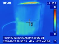
| The front of the PS3 didn't heat up as quickly, as we can see in the next picture. The only slightly warm part is the PS3's power supply in the lower left corner of the console as seen: |
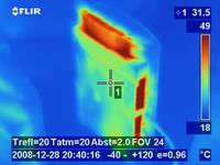
| The next image also shows the front of the PS3, but from a slightly elevated angle to show the top/side vents in comparison to the PSU. |
| Now after waiting some time (7 minutes into testing), we can already see the back and side vents getting quite hot, going as high as 49 C. This is where the heatsink is sitting mostly. |
Now we waited for the PS3 to REALLY heat up. Using Folding@Home, the PS3 is put under a lot of stress, although different to gaming, because the RSX is supposedly not put under as much stress. This was done because it was easier to get a uniform heat output from the system, as various games tax the system's components in different ways and at different times, being that they are not linear.
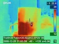
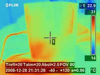
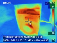
| Sadly, in this pic, the FLIR camera was not calibrated correctly (you have to calibrate it before every pic), so it seems that the PS3 is much hotter than it really is. The heat gauge on the side tells us the actual max temp on this pic is only 29 C. Still, we can gather from this pic that only the PSU is getting hot, and the rest of the console is uniformly orange. |
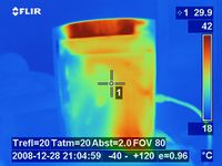
| The backside shows a different picture. The rear vents are now very warm at 45 C, compared to the rest at about 23 C, which is slightly above room temperature. |
| Here is the backside of the PS3 after heating up. The complete bottom is getting pretty hot, but the most heat output can still be seen at the side vent, which is at 42 C. |
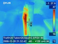
| Now that we know the temperature of the 60GB after being given time to warm up under load, we connected the 40GB unit to the TV. Starting again at about 22 C, we can again see the PSU heating up from the front. |
| After only several minutes under load, we get this picture, showing us the heat production compared to the 60GB is nearly the same at the rear vents at 47 C. |
| Now we looked at the bottom, and it looked quite different compared to the 60GB. Here we can actually see where the fan is located, and we can see that the distribution of heat is much more uniform. This tells us that the heatsink in the 40GB PS3's is much more efficient, even though the overall heat output is about the same. The 40GB is also a lot quieter. My 60GB unit's spins up to high speed mode quick and stays that way. The 40GB's fan speed nearly always stays one "notch" lower, making it nearly silent when gaming or watching a movie. The back of the unit is also a bit cooler than the 60GB, though the side is about the same. You'll notice fewer deep reds on the 40GB images in comparison to the images of the 60GB console. |
The verdict is still a bit hard to deduce. After all, we know that the CELL in the 40GB is 65nm compared to the 90nm chip in the 60GB consoles, also using about 40 Watts less power overall. Yet, the heat signature is almost the same for both, being slightly more uniform in the 40GB. My guess is, the 40GB does indeed produce less heat, as can be deduced by the much lower weight and smaller heatsink. Thus, it can more effectively transport heat away than the older 60GB model.
All in all, I say, Sony engineered quite a nice little piece of machinery here in terms of heat production and dissipation. Today's laptops have CPU's which usually produce less than 25 Watts of heat under load, normally never exceeding 35 watts. PS3 on the other hand can use up to 200 Watts in a case that is not that much bigger.
source: http://psinsider.e-mpire.com/index.php?categoryid=3&m_articles_articleid=1160
Other
The Misdiagnosis of the PlayStation 3 Yellow Light of Death
| |||||||||||||||||||||||||||||||||||||||||||||||||||||||||||||||||||||||||||||||||||||||||||||||||||||||||||||||||||||||||||||||||||||||||||||||||||||||||||||||||||||||||||||


