MN8647091: Difference between revisions

From PS3 Developer wiki
Jump to navigation Jump to search
Tag: Replaced
 
(8 intermediate revisions by the same user not shown)
Line 12: Line 12:
**[[CECH-43xx]] with [[REX-001]] motherboard.


== Pinout ==
{{Template:HDMI Controller pinout TQFP 100 pins‎}}
<!-- https://www.psdevwiki.com/ps3/File:HDMI_pads_as_seen_on_JTP-001_-_%28Mr.Dutch%29.jpg -->
 
*Most of the data pins in between 31-91 are inputs. Connected to [[RSX]] pad ??? ([[Template:RSX pad layout 41x41|RSX layout 41x41]]), or pad ??? ([[Template:RSX pad layout 34x34|RSX layout 34x34]])
 
{|class="wikitable mw-datatable" style="width:100%; line-height:120%; font-size:90%"
|+ HDMI Controller pinout 100 pins
! style="width:0px; padding:0px" | Pin !! style="width:0px" | Name !! style="width:0px; padding:0px" | Type !! Description
|-
| 1 ||  ||  ||
|-
| 2 || {{cellcolors|#333333|#ffffff}} GND || {{pin}} ||
|-
| 3 ||  ||  || Connected to [[Connectors#HDMI_Out|HDMI connector]] pin ? (CEC control ?)
|-
| 4 || {{cellcolors|#ff8833|#ffffff}} HDMI_VCC2 || {{pin}} || Connected to voltage regulator [[Talk:Regulators|Mitsumi 348A]] pin 5
|-
| 5 || {{cellcolors|#333333|#ffffff}} GND || {{pin}} ||
|-
| 6 ||  ||  ||
|-
| 7 || {{cellcolors|#333333|#ffffff}} GND || {{pin}} ||
|-
| 8 ||  ||  ||
|-
| 9 || {{cellcolors|#ff8833|#ffffff}} HDMI_VCC2 || {{pin}} || Connected to voltage regulator [[Talk:Regulators|Mitsumi 348A]] pin 5
|-
| 10 || {{cellcolors|#ff8}} TMDS_CLOCK- || {{pino}} || Connected to [[Connectors#HDMI_Out|HDMI connector]] pin 12 throught an EMI filter
|-
| 11 || {{cellcolors|#333333|#ffffff}} GND || {{pin}} || Connected to [[Connectors#HDMI_Out|HDMI connector]] pin 11
|-
| 12 || {{cellcolors|#ff8}} TMDS_CLOCK+ || {{pino}} || Connected to [[Connectors#HDMI_Out|HDMI connector]] pin 10 throught an EMI filter
|-
| 13 || {{cellcolors|#ff8833|#ffffff}} HDMI_VCC2 || {{pin}} || Connected to voltage regulator [[Talk:Regulators|Mitsumi 348A]] pin 5
|-
| 14 || {{cellcolors|#ff8}} TMDS_DATA0- || {{pino}} || Connected to [[Connectors#HDMI_Out|HDMI connector]] pin 9 throught an EMI filter
|-
| 15 || {{cellcolors|#333333|#ffffff}} GND || {{pin}} || Connected to [[Connectors#HDMI_Out|HDMI connector]] pin 8
|-
| 16 || {{cellcolors|#ff8}} TMDS_DATA0+ || {{pino}} || Connected to [[Connectors#HDMI_Out|HDMI connector]] pin 7 throught an EMI filter
|-
| 17 || {{cellcolors|#ff8833|#ffffff}} HDMI_VCC2 || {{pin}} || Connected to voltage regulator [[Talk:Regulators|Mitsumi 348A]] pin 5
|-
| 18 || {{cellcolors|#ff8}} TMDS_DATA1- || {{pino}} || Connected to [[Connectors#HDMI_Out|HDMI connector]] pin 6 throught an EMI filter
|-
| 19 || {{cellcolors|#333333|#ffffff}} GND || {{pin}} || Connected to [[Connectors#HDMI_Out|HDMI connector]] pin 5
|-
| 20 || {{cellcolors|#ff8}} TMDS_DATA1+ || {{pino}} || Connected to [[Connectors#HDMI_Out|HDMI connector]] pin 4 throught an EMI filter
|-
| 21 || {{cellcolors|#ff8833|#ffffff}} HDMI_VCC2 || {{pin}} || Connected to voltage regulator [[Talk:Regulators|Mitsumi 348A]] pin 5
|-
| 22 || {{cellcolors|#ff8}} TMDS_DATA2- || {{pino}} || Connected to [[Connectors#HDMI_Out|HDMI connector]] pin 3 throught an EMI filter
|-
| 23 || {{cellcolors|#333333|#ffffff}} GND || {{pin}} || Connected to [[Connectors#HDMI_Out|HDMI connector]] pin 2
|-
| 24 || {{cellcolors|#ff8}} TMDS_DATA2+ || {{pino}} || Connected to [[Connectors#HDMI_Out|HDMI connector]] pin 1 throught an EMI filter
|-
| 25 || {{cellcolors|#ff8833|#ffffff}} HDMI_VCC2 || {{pin}} || Connected to voltage regulator [[Talk:Regulators|Mitsumi 348A]] pin 5
|-
! colspan="3" style="padding:1px" data-sort-value="25.5"|
|-
| 26 || {{cellcolors|#ff8833|#ffffff}} HDMI_VCC2 || {{pin}} || Connected to voltage regulator [[Talk:Regulators|Mitsumi 348A]] pin 5
|-
| 27 || {{cellcolors|#6666ff|#ffff00}} HDMI_I2C_SCL || {{pini}} || Connected to [[Syscon Hardware|Syscon]] [[Template:Syscon_pinout_LQFP_128_pins|SW2-30x]] pin 1, or  [[Template:Syscon_pinout_LQFP_100_pins|SW3-30x]] pin 1
|-
| 28 || {{cellcolors|#333333|#ffffff}} GND || {{pin}} ||
|-
| 29 || {{cellcolors|#6666ff|#ffff00}} HDMI_I2C_SDA || {{pinio}} || Connected to [[Syscon Hardware|Syscon]] [[Template:Syscon_pinout_LQFP_128_pins|SW2-30x]]  pin 128, or  [[Template:Syscon_pinout_LQFP_100_pins|SW3-30x]] pin 100
|-
| 30 || {{cellcolors|#ff3333|#ffffff}} HDMI_VCC1 || {{pin}} || Connected to voltage regulator [[Talk:Regulators|Mitsumi 348A]] pin 4
|-
| 31 ||  ||  ||
|-
| 32 ||  ||  ||
|-
| 33 ||  ||  ||
|-
| 34 || {{cellcolors|#333333|#ffffff}} GND || {{pin}} ||
|-
| 35 ||  ||  ||
|-
| 36 ||  ||  ||
|-
| 37 ||  ||  ||
|-
| 38 || {{cellcolors|#ff8833|#ffffff}} HDMI_VCC2 || {{pin}} || Connected to voltage regulator [[Talk:Regulators|Mitsumi 348A]] pin 5
|-
| 39 ||  ||  ||
|-
| 40 ||  ||  ||
|-
| 41 ||  ||  ||
|-
| 42 || {{cellcolors|#ff3333|#ffffff}} HDMI_VCC1 || {{pin}} || Connected to voltage regulator [[Talk:Regulators|Mitsumi 348A]] pin 4
|-
| 43 ||  ||  ||
|-
| 44 ||  ||  ||
|-
| 45 ||  ||  ||
|-
| 46 || {{cellcolors|#333333|#ffffff}} GND || {{pin}} ||
|-
| 47 ||  ||  ||
|-
| 48 ||  ||  ||
|-
| 49 ||  ||  ||
|-
| 50 || {{cellcolors|#ff3333|#ffffff}} HDMI_VCC1 || {{pin}} || Connected to voltage regulator [[Talk:Regulators|Mitsumi 348A]] pin 4
|-
! colspan="3" style="padding:1px" data-sort-value="50.5"|
|-
| 51 ||  ||  ||
|-
| 52 ||  ||  ||
|-
| 53 ||  ||  ||
|-
| 54 ||  ||  ||
|-
| 55 ||  ||  ||
|-
| 56 ||  ||  ||
|-
| 57 || {{cellcolors|#ff8833|#ffffff}} HDMI_VCC2 || {{pin}} || Connected to voltage regulator [[Talk:Regulators|Mitsumi 348A]] pin 5
|-
| 58 ||  ||  ||
|-
| 59 ||  ||  ||
|-
| 60 ||  ||  ||
|-
| 61 || {{cellcolors|#333333|#ffffff}} GND || {{pin}} ||
|-
| 62 ||  ||  ||
|-
| 63 ||  ||  ||
|-
| 64 ||  ||  ||
|-
| 65 || {{cellcolors|#ff3333|#ffffff}} HDMI_VCC1 || {{pin}} || Connected to voltage regulator [[Talk:Regulators|Mitsumi 348A]] pin 4
|-
| 66 ||  ||  ||
|-
| 67 ||  ||  ||
|-
| 68 ||  ||  ||
|-
| 69 || {{cellcolors|#333333|#ffffff}} GND || {{pin}} ||
|-
| 70 ||  ||  ||
|-
| 71 ||  ||  ||
|-
| 72 ||  ||  ||
|-
| 73 || {{cellcolors|#ff3333|#ffffff}} HDMI_VCC1 || {{pin}} || Connected to voltage regulator [[Talk:Regulators|Mitsumi 348A]] pin 4
|-
| 74 ||  ||  ||
|-
| 75 ||  ||  ||
|-
! colspan="3" style="padding:1px" data-sort-value="75.5"|
|-
| 76 ||  ||  ||
|-
| 77 || {{cellcolors|#ff8833|#ffffff}} HDMI_VCC2 || {{pin}} || Connected to voltage regulator [[Talk:Regulators|Mitsumi 348A]] pin 5
|-
| 78 ||  ||  ||
|-
| 79 ||  ||  ||
|-
| 80 ||  ||  ||
|-
| 81 ||  ||  ||
|-
| 82 || {{cellcolors|#ff3333|#ffffff}} HDMI_VCC1 || {{pin}} || Connected to voltage regulator [[Talk:Regulators|Mitsumi 348A]] pin 4
|-
| 83 ||  ||  ||
|-
| 84 ||  ||  ||
|-
| 85 ||  ||  ||
|-
| 86 ||  ||  ||
|-
| 87 || {{cellcolors|#ff8833|#ffffff}} HDMI_VCC2 || {{pin}} || Connected to voltage regulator [[Talk:Regulators|Mitsumi 348A]] pin 5
|-
| 88 ||  ||  ||
|-
| 89 ||  ||  ||
|-
| 90 || {{cellcolors|#333333|#ffffff}} GND || {{pin}} ||
|-
| 91 ||  ||  ||
|-
| 92 || {{cellcolors|#ff3333|#ffffff}} HDMI_VCC1 || {{pin}} || Connected to voltage regulator [[Talk:Regulators|Mitsumi 348A]] pin 4
|-
| 93 || ? || ? || Connected to [[Syscon Hardware|Syscon]] [[Template:Syscon_pinout_LQFP_128_pins|SW2-30x]]  pin 124, or [[Template:Syscon_pinout_LQFP_100_pins|SW3-30x]] pin 46 ?
|-
| 94 ||  ||  || Related with pin 93 ?
|-
| 95 ||  ||  || Not related with pins 93 and 94 ?
|-
| 96 || {{cellcolors|#ff8}} HOTPLUG_DET ||  || Connected to [[Connectors#HDMI_Out|HDMI connector]] pin 19
|-
| 97 || {{cellcolors|#6666ff|#ffff00}} DDC_I2C_SDA ||  || Connected to [[Connectors#HDMI_Out|HDMI connector]] pin 16
|-
| 98 || {{cellcolors|#6666ff|#ffff00}} DDC_I2C_SCL ||  || Connected to [[Connectors#HDMI_Out|HDMI connector]] pin 15
|-
| 99 || {{cellcolors|#ff8833|#ffffff}} HDMI_VCC2 || {{pin}} || Connected to voltage regulator [[Talk:Regulators|Mitsumi 348A]] pin 5
|-
| 100 || {{cellcolors|#ff3333|#ffffff}} HDMI_VCC1 || {{pin}} || Connected to voltage regulator [[Talk:Regulators|Mitsumi 348A]] pin 4
|}


{{Motherboard Components}}<noinclude>[[Category:Main]]</noinclude>

Latest revision as of 06:43, 8 June 2022

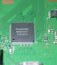
Panasonic MN8647091[edit | edit source]

Panasonic MN8647091


Pinout


Panasonic MN8647091

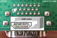
HDMI connector pads

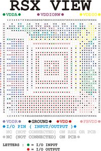
RSX 41x41 pad layout

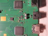
Mitsumi 348A and
Intersil ISL4353C
Seen on a JSD-001 motherboard
[ View ], [ Discuss ] or [ Edit ]
HDMI Controller pinout TQFP 100 pins
Pin Name Type Description
1 N/C ?
Not Connected
Not connected ?
2 GND
Others
3 CEC
In/Out
Connected to HDMI connector pin 13 (Consumer Electronics Control)
4 HDMI_VCC2
Others
Connected to voltage regulator Mitsumi 348A pin 5
5 GND
Others
6 N/C ?
Not Connected
Not connected ?
7 GND
Others
8 N/C ?
Not Connected
Not connected ?
9 HDMI_VCC2
Others
Connected to voltage regulator Mitsumi 348A pin 5
10 CK-
In
Connected to HDMI connector pin 12 throught an EMI filter
11 CKG
Others
Connected to HDMI connector pin 11
12 CK+
Out
Connected to HDMI connector pin 10 throught an EMI filter
13 HDMI_VCC2
Others
Connected to voltage regulator Mitsumi 348A pin 5
14 D0-
In
Connected to HDMI connector pin 9 throught an EMI filter
15 D0G
Others
Connected to HDMI connector pin 8
16 D0+
Out
Connected to HDMI connector pin 7 throught an EMI filter
17 HDMI_VCC2
Others
Connected to voltage regulator Mitsumi 348A pin 5
18 D1-
In
Connected to HDMI connector pin 6 throught an EMI filter
19 D1G
Others
Connected to HDMI connector pin 5
20 D1+
Out
Connected to HDMI connector pin 4 throught an EMI filter
21 HDMI_VCC2
Others
Connected to voltage regulator Mitsumi 348A pin 5
22 D2-
In
Connected to HDMI connector pin 3 throught an EMI filter
23 D2G
Others
Connected to HDMI connector pin 2
24 D2+
Out
Connected to HDMI connector pin 1 throught an EMI filter
25 HDMI_VCC2
Others
Connected to voltage regulator Mitsumi 348A pin 5
26 HDMI_VCC2
Others
Connected to voltage regulator Mitsumi 348A pin 5
27 HDMI_I2C_SCL
In
Connected to Syscon pin 1 (LQFP 128 pins layout), or pin 1 (LQFP 100 pins layout)
28 GND
Others
29 HDMI_I2C_SDA
In/Out
Connected to Syscon pin 128 (LQFP 128 pins layout), or pin 100 (LQFP 100 pins layout)
30 HDMI_VCC1
Others
Connected to voltage regulator Mitsumi 348A pin 4
31 Connected to RSX pad ? (RSX layout 41x41), or pad ? (RSX layout 34x34)
32
33
34 GND
Others
35
36
37
38 HDMI_VCC2
Others
Connected to voltage regulator Mitsumi 348A pin 5
39
40
41
42 HDMI_VCC1
Others
Connected to voltage regulator Mitsumi 348A pin 4
43
44
45
46 GND
Others
47
48
49
50 HDMI_VCC1
Others
Connected to voltage regulator Mitsumi 348A pin 4
51
52
53
54
55
56
57 HDMI_VCC2
Others
Connected to voltage regulator Mitsumi 348A pin 5
58
59
60
61 GND
Others
62
63
64
65 HDMI_VCC1
Others
Connected to voltage regulator Mitsumi 348A pin 4
66
67
68
69 GND
Others
70
71
72
73 HDMI_VCC1
Others
Connected to voltage regulator Mitsumi 348A pin 4
74
75
76
77 HDMI_VCC2
Others
Connected to voltage regulator Mitsumi 348A pin 5
78
79
80
81
82 HDMI_VCC1
Others
Connected to voltage regulator Mitsumi 348A pin 4
83
84
85
86 Connected to Intersil ISL4353C optical audio pin 24
87 HDMI_VCC2
Others
Connected to voltage regulator Mitsumi 348A pin 5
88 Connected to Intersil ISL4353C optical audio pin 1
89 Connected to Intersil ISL4353C optical audio pin 23
90 GND
Others
91
92 HDMI_VCC1
Others
Connected to voltage regulator Mitsumi 348A pin 4
93 Connected to Syscon pin 124 (LQFP 128 pins layout), or pin 93 ? (LQFP 100 pins layout)
94 Connected to Syscon pin 15 (LQFP 128 pins layout), or pin 5 (LQFP 100 pins layout)
95 Connected to Syscon pin 120 (LQFP 128 pins layout) through 3.6K resistor, or pin 46 (LQFP 100 pins layout)
96 HPD
In
Connected to HDMI connector pin 19 (HOTPLUG_DET)
97 DDDATA
In/Out
Connected to HDMI connector pin 16 (Display Data Channel, data)
98 DDCLK
Out
Connected to HDMI connector pin 15 (Display Data Channel, clock)
99 HDMI_VCC2
Others
Connected to voltage regulator Mitsumi 348A pin 5
100 HDMI_VCC1
Others
Connected to voltage regulator Mitsumi 348A pin 4