Internal: Difference between revisions
Jump to navigation
Jump to search
mNo edit summary |
CelesteBlue (talk | contribs) |
||
| (12 intermediate revisions by 4 users not shown) | |||
| Line 1: | Line 1: | ||
== Internal Pads == | == Internal Pads == | ||
<gallery> | <gallery> | ||
File:CUH-10xxA - SAA-001 - pads-1.png|[[CUH-10xxA]] [[SAA-001]] [[#pads 1 (GbLAN)|pads 1 (GbLAN)]] | File:CUH-10xxA - SAA-001 - pads-1.png|[[CUH-10xxA]] [[SAA-001]] [[#pads 1 (GbLAN)|pads 1 (GbLAN)]] | ||
File:CUH-10xxA - SAA-001 - pads-2.png|[[CUH-10xxA]] [[SAA-001]] [[#pads 2 ( | File:CUH-10xxA - SAA-001 - pads-2.png|[[CUH-10xxA]] [[SAA-001]] [[#pads 2 (Southbridge)|pads 2 (Southbridge)]] | ||
File:CUH-10xxA - SAA-001 - pads-3.png|[[CUH-10xxA]] [[SAA-001]] [[#pads 3 (A01- | File:CUH-10xxA - SAA-001 - pads-3.png|[[CUH-10xxA]] [[SAA-001]] [[#pads 3 (A01-COL)|pads 3 (A01-COL)]] | ||
</gallery> | </gallery> | ||
It is not documented yet what use the pads have (e.g. [[Service Connectors]], SPI, I2C, JTAG, [[PCIe]] etc.) | |||
=== pads 1 (GbLAN) === | === pads 1 (GbLAN) === | ||
<div style="float:right">[[File:CUH-10xxA - SAA-001 - 14 pins port - img1.jpg|200px|thumb|left|[[CUH-10xxA]] [[SAA-001]] pads1/14 pins - img1]]<br />[[File:CUH-10xxA - SAA-001 - 14 pins port - img2.jpg|200px|thumb|left|[[CUH-10xxA]] [[SAA-001]] pads1/14 pins - img1]]</div> | <div style="float:right">[[File:CUH-10xxA - SAA-001 - 14 pins port - img1.jpg|200px|thumb|left|[[CUH-10xxA]] [[SAA-001]] pads1/14 pins - img1]]<br />[[File:CUH-10xxA - SAA-001 - 14 pins port - img2.jpg|200px|thumb|left|[[CUH-10xxA]] [[SAA-001]] pads1/14 pins - img1]]</div> | ||
[[GbLAN]] MDIO | [[GbLAN]] MDIO | ||
{| border="1" cellspacing="0" cellpadding="5" border="#999" class="wikitable" style="border:1px solid #999; border-collapse: collapse;" | {| border="1" cellspacing="0" cellpadding="5" border="#999" class="wikitable" style="border:1px solid #999; border-collapse: collapse;" | ||
|- bgcolor="#cccccc" | |- bgcolor="#cccccc" | ||
| Line 42: | Line 45: | ||
|- | |- | ||
| 14 || Gnd || Internal ground | | 14 || Gnd || Internal ground | ||
| | |} | ||
=== pads 2 (Southbridge) === | |||
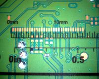
<div style="float:right">[[File:CUH-10xxA - SAA-001 - 20 pins port - img1.jpg|200px|thumb|left|[[CUH-10xxA]] [[SAA-001]] pads2/20 pins - img1]]<br />[[File:CUH-10xxA - SAA-001 - 20 pins port - img2.jpg|200px|thumb|left|[[CUH-10xxA]] [[SAA-001]] pads2/20 pins - img2]]</div> | <div style="float:right">[[File:CUH-10xxA - SAA-001 - 20 pins port - img1.jpg|200px|thumb|left|[[CUH-10xxA]] [[SAA-001]] pads2/20 pins - img1]]<br />[[File:CUH-10xxA - SAA-001 - 20 pins port - img2.jpg|200px|thumb|left|[[CUH-10xxA]] [[SAA-001]] pads2/20 pins - img2]]</div> | ||
[[ | [[Southbridge]] debug (No activity was detected so far. It looks to be disabled / turned off) | ||
{| border="1" cellspacing="0" cellpadding="5" border="#999" class="wikitable" style="border:1px solid #999; border-collapse: collapse;" | {| border="1" cellspacing="0" cellpadding="5" border="#999" class="wikitable" style="border:1px solid #999; border-collapse: collapse;" | ||
|- bgcolor="#cccccc" | |- bgcolor="#cccccc" | ||
| Line 91: | Line 94: | ||
|- | |- | ||
| 20 || Vcc || +3.3V_STBY power (always on, including the deep standby) | | 20 || Vcc || +3.3V_STBY power (always on, including the deep standby) | ||
|- | |} | ||
=== pads 3 (A01-COL) === | |||
<div style="float:right">[[File:CUH-10xxA - SAA-001 - 30 pins port - img1.jpg|200px|thumb|left|[[CUH-10xxA]] [[SAA-001]] pads3/30 pins - img1]]<br />[[File:CUH-10xxA - SAA-001 - 30 pins port - img2.jpg|200px|thumb|left|[[CUH-10xxA]] [[SAA-001]] pads3/30 pins - img2]]</div> | <div style="float:right">[[File:CUH-10xxA - SAA-001 - 30 pins port - img1.jpg|200px|thumb|left|[[CUH-10xxA]] [[SAA-001]] pads3/30 pins - img1]]<br />[[File:CUH-10xxA - SAA-001 - 30 pins port - img2.jpg|200px|thumb|left|[[CUH-10xxA]] [[SAA-001]] pads3/30 pins - img2]]</div> | ||
[[A01- | [[A01-COL]] | ||
{| border="1" cellspacing="0" cellpadding="5" border="#999" class="wikitable" style="border:1px solid #999; border-collapse: collapse;" | {| border="1" cellspacing="0" cellpadding="5" border="#999" class="wikitable" style="border:1px solid #999; border-collapse: collapse;" | ||
|- bgcolor="#cccccc" | |- bgcolor="#cccccc" | ||
| Line 160: | Line 163: | ||
|- | |- | ||
| 30 || || | | 30 || || | ||
|} | |||
== UART == | |||
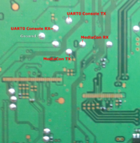
<div style="float:right">[[File:UART0 Console - UART MediaCon.png|200px|thumb|left|UART0 Console - [[Southbridge]] UART, as seen on [[SAA-001]] (same layout on [[SAA-K23]], [[SAB-K02]] and [[SAB-001]])]]</div> | |||
Same layout is used for [[SAA-K23]], [[SAB-K02]] / [[SAA-001]], [[SAB-001]] (pads are present on [[SAC-001]] too, but layout slightly differs) | |||
3.3V CMOS TTL - 115200, n, 8.1 | |||
* [http://jaicrab.org/Ps4/Tools/UART/JaiBrute2.zip JaiBrute v2] {{MD5|f71e4beebbbb859f74dc536c9e824acb}} | |||
* [http://jaicrab.org/Ps4/Tools/UART/JaiBrute.zip JaiBrute v1] {{MD5|f7a7e0f970d5e86ef110d2d4ff0ed1b1}} | |||
=== UART0 Console === | |||
{| border="1" cellspacing="0" cellpadding="5" border="#999" class="wikitable" style="border:1px solid #999; border-collapse: collapse;" | |||
|- bgcolor="#cccccc" | |||
! Pin !! Name !! Description | |||
|- | |||
| || GND || Ground | |||
|- | |||
| || U0C_TX || UART0 Console Transmit | |||
|- | |- | ||
|} | | || U0C_RX || UART0 Console Receive | ||
|} | |||
'''Note:''' You have to enable debug logs as by default the output is zeroed out by "spaces" on CEX consoles. You can enable UART0 logs by patching Serial Flash [[Non Volatile Storage]]. You can also use UART Enabler kernel plugin by SiSTRo. | |||
=== Southbridge UART === | |||
{| border="1" cellspacing="0" cellpadding="5" border="#999" class="wikitable" style="border:1px solid #999; border-collapse: collapse;" | |||
|- bgcolor="#cccccc" | |||
! Pin !! Name !! Description | |||
|- | |||
| || GND || Ground | |||
|- | |||
| || TX || Southbridge UART Transmit | |||
|- | |||
| || RX || Southbridge UART Receive | |||
|} | |||
'''Note:''' quite similar to [http://www.psdevwiki.com/ps3/Syscon_Hardware#Syscon_UART PS3 Syscon UART] | |||
{{Motherboard Components}} | {{Motherboard Components}} | ||
<noinclude>[[Category:Main]]</noinclude> | <noinclude>[[Category:Main]]</noinclude> | ||
Latest revision as of 00:50, 10 July 2023
Internal Pads[edit | edit source]
It is not documented yet what use the pads have (e.g. Service Connectors, SPI, I2C, JTAG, PCIe etc.)
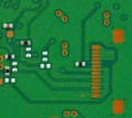
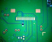
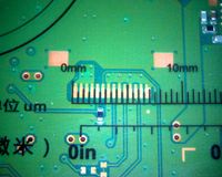
pads 1 (GbLAN)[edit | edit source]
GbLAN MDIO
| Pin | Name | Description |
|---|---|---|
| 1 | Vcc | Internal +5V |
| 2 | Vcc | Internal +5V |
| 3 | Vcc | Internal +5V |
| 4 | Vcc | Internal +5V |
| 5 | ||
| 6 | ||
| 7 | Gnd | Internal ground |
| 8 | ||
| 9 | Gnd | Internal ground |
| 10 | ||
| 11 | Gnd | Internal ground |
| 12 | ||
| 13 | Gnd | Internal ground |
| 14 | Gnd | Internal ground |
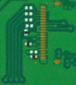
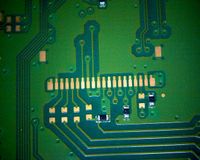
pads 2 (Southbridge)[edit | edit source]
Southbridge debug (No activity was detected so far. It looks to be disabled / turned off)
| Pin | Name | Description |
|---|---|---|
| 1 | ||
| 2 | Gnd | Internal ground |
| 3 | ||
| 4 | ||
| 5 | ||
| 6 | ||
| 7 | ||
| 8 | Gnd | Internal ground |
| 9 | ||
| 10 | Gnd | Internal ground |
| 11 | 3.3V when console is started | |
| 12 | ||
| 13 | ||
| 14 | ||
| 15 | ||
| 16 | ||
| 17 | Gnd | Internal ground |
| 18 | ||
| 19 | Gnd | Internal ground |
| 20 | Vcc | +3.3V_STBY power (always on, including the deep standby) |
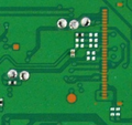
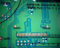
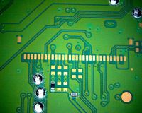
pads 3 (A01-COL)[edit | edit source]
| Pin | Name | Description |
|---|---|---|
| 1 | ||
| 2 | ||
| 3 | ||
| 4 | ||
| 5 | ||
| 6 | Gnd | Internal ground |
| 7 | I2C | I2C bus (100 kHz clock) |
| 8 | Gnd | Internal ground |
| 9 | ||
| 10 | ||
| 11 | ||
| 12 | ||
| 13 | Gnd | Internal ground |
| 14 | ||
| 15 | ||
| 16 | ||
| 17 | Gnd | Internal ground |
| 18 | ||
| 19 | ||
| 20 | ||
| 21 | ||
| 22 | Gnd | Internal ground |
| 23 | ||
| 24 | ||
| 25 | Gnd | Internal ground |
| 26 | ||
| 27 | ||
| 28 | ||
| 29 | ||
| 30 |
UART[edit | edit source]
Same layout is used for SAA-K23, SAB-K02 / SAA-001, SAB-001 (pads are present on SAC-001 too, but layout slightly differs)
3.3V CMOS TTL - 115200, n, 8.1
UART0 Console[edit | edit source]
| Pin | Name | Description |
|---|---|---|
| GND | Ground | |
| U0C_TX | UART0 Console Transmit | |
| U0C_RX | UART0 Console Receive |
Note: You have to enable debug logs as by default the output is zeroed out by "spaces" on CEX consoles. You can enable UART0 logs by patching Serial Flash Non Volatile Storage. You can also use UART Enabler kernel plugin by SiSTRo.
Southbridge UART[edit | edit source]
| Pin | Name | Description |
|---|---|---|
| GND | Ground | |
| TX | Southbridge UART Transmit | |
| RX | Southbridge UART Receive |
Note: quite similar to PS3 Syscon UART
| ||||||||||||||||||||||||||||||||||||||||||||||||||||||||||||||||||||||||||||||
