MX25L25635FMI-10G
Jump to navigation
Jump to search
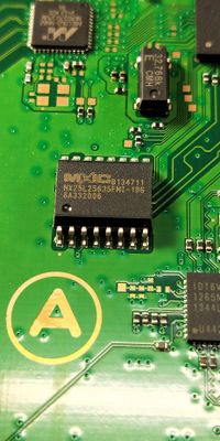
The Macronix MX25L25635FMI-10G is a 256Mb NOR Serial Flash present on some PS4 motherboard.
- 3V 256M-BIT [x 1/x 2/x 4] CMOS MXSMIO (SERIAL MULTI I/O) 16-SOP (300mil)
- Seen on SAA-001, SAB-001.
- MX25L25635F datasheet
- Technical Note: Migrating from Macronix's MX25L25635F to Micron's N25Q 256Mb Flash Device
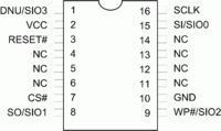
Pinout[edit | edit source]
| Pin | 1x I/O | 2x I/O | 4x I/O | Description | |
|---|---|---|---|---|---|
| S3 | 1 | DNU | DNU | SIO3 | Do not use or Serial Data Input & Output (for 4xI/O read mode) |
| 3.3 | 2 | VCC | VCC | VCC | +3.3V DC Power Supply |
| RS | 3 | RESET# | RESET# | RESET# | Hardware Reset Pin Active low |
| 4 | NC | NC | NC | No Connection | |
| 5 | NC | NC | NC | No Connection | |
| 6 | NC | NC | NC | No Connection | |
| CS | 7 | CS# | CS# | CS# | Chip Select |
| S1 | 8 | SO | SIO1 | SIO1 | Serial Data Output (for 1 x I/O) or Serial Data Input & Output (for 2x I/O or 4x I/O read mode) |
| S2 | 9 | WP# | WP# | SIO2 | Write Protection: connect to GND or Serial Data Input & Output (for 4x I/O read mode) |
| GND | 10 | GND | GND | GND | Ground |
| 11 | NC | NC | NC | No Connection | |
| 12 | NC | NC | NC | No Connection | |
| 13 | NC | NC | NC | No Connection | |
| 14 | NC | NC | NC | No Connection | |
| S0 | 15 | SI | SIO0 | SIO0 | Serial Data Input (for 1 x I/O) or Serial Data Input & Output (for 2x I/O or 4x I/O read mode) |
| SC | 16 | SCLK | SCLK | SCLK | Clock Input |
Spare parts[edit | edit source]
Hardware read/write[edit | edit source]
Hints[edit | edit source]
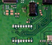
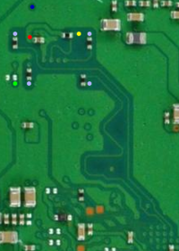
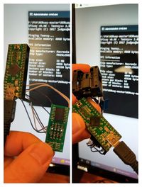
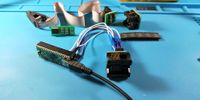
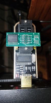
On Board Dumping does not work as it requires the VCC pin lifted. To Read/Write the chip in the safest way possible, you need to desolder the Macronix Serial Flash from the PS4 motherboard and use an external flasher like the Teensy and SPIway or the Raspberry Pi and JAISPI. For the desoldering part you should only heat up the pins of the chip thanks to a Hot Air SMD Rework Station and a nozzle.
Flashing Examples[edit | edit source]
| ||||||||||||||||||||||||||||||||||||||||||||||||||||||||||||||||||||||||||||||
