MX25L1006E: Difference between revisions
Jump to navigation
Jump to search
mNo edit summary |
mNo edit summary |
||
| Line 11: | Line 11: | ||
=== Pinout === | === Pinout === | ||
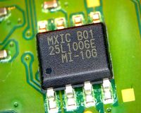
<div style="float:right">[[File:MX25L1006E Pinout.png|200px|thumb|left|MX25L1006E Pinout]]</div> | <div style="float:right">[[File:MX25L1006E Pinout.png|200px|thumb|left|MX25L1006E Pinout]]<br />[[File:CUH-10xxA - SAA-001 - Macronix MX25L1006E - markings- MXIC B01 25L1006EMI-10G.jpg|200px|thumb|left|[[CUH-10xxA]] [[SAA-001]] Macronix [[MX25L1006E]] - markings: MXIC B01 25L1006EMI-10G]]</div> | ||
{| border="1" cellspacing="0" cellpadding="5" border="#999" class="wikitable" style="border:1px solid #999; border-collapse: collapse;" | {| border="1" cellspacing="0" cellpadding="5" border="#999" class="wikitable" style="border:1px solid #999; border-collapse: collapse;" | ||
|- bgcolor="#cccccc" | |- bgcolor="#cccccc" | ||
Latest revision as of 12:31, 17 January 2014
Macronix MX25L1006E[edit | edit source]
3V 1M-BIT [x 1/x 2] CMOS SERIAL FLASH
http://postar.sino-star.com/public/uploads/20120412174638_676.pdf
Current photos are a but too grainy, but there are 2 of these on the board. One near the SATA on the back of the board (colored blue @ ifixit) and one near the front USB.
Pinout[edit | edit source]
| Pin | 1x I/O | 2x I/O | Description |
|---|---|---|---|
| 1 | CS# | CS# | Chip Select |
| 2 | SO | SIO1 | Serial Data Output (for 1 x I/O) or Serial Data Input & Output (for 2x I/O) |
| 3 | WP# | WP# | Write Protection: connect to GND |
| 4 | GND | GND | Ground |
| 5 | SI | SIO0 | Serial Data Input (for 1 x I/O) or Serial Data Input & Output (for 2x I/O) |
| 6 | SCLK | SCLK | Clock Input |
| 7 | HOLD# | HOLD# | Hold, to pause the device without deselecting the device |
| 8 | VCC | VCCS | +3V DC Power Supply |
| ||||||||||||||||||||||||||||||||||||||||||||||||||||||||||||||||||||||||||||||


