MX25L25635FMI-10G: Difference between revisions
Jump to navigation
Jump to search
mNo edit summary |
mNo edit summary |
||
| Line 7: | Line 7: | ||
=== Pinout === | === Pinout === | ||
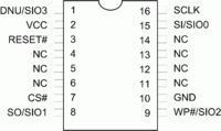
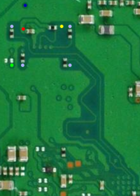
<div style="float:right">[[File:MX25L25635FMI-10G Pinout.png|200px|thumb|left|MX25L25635FMI-10G Pinout]]</div> | <div style="float:right">[[File:MX25L25635FMI-10G Pinout.png|200px|thumb|left|MX25L25635FMI-10G Pinout]]<br />[[File:MX25L25635FMI-10G Removed - SAA-001 - componentside.png|200px|thumb|left|MX25L25635FMI-10G Removed - SAA-001 - componentside]]<br />[[File:MX25L25635FMI-10G - SAA-001 - backside.png|200px|thumb|left|MX25L25635FMI-10G - SAA-001 - backside]]</div> | ||
{| border="1" cellspacing="0" cellpadding="5" border="#999" class="wikitable" style="border:1px solid #999; border-collapse: collapse;" | {| border="1" cellspacing="0" cellpadding="5" border="#999" class="wikitable" style="border:1px solid #999; border-collapse: collapse;" | ||
|- bgcolor="#cccccc" | |- bgcolor="#cccccc" | ||
! Pin !! 1x I/O !! 2x I/O !! 4x I/O !! Description | ! !! Pin !! 1x I/O !! 2x I/O !! 4x I/O !! Description | ||
|- | |- | ||
| 1 || style="color:white; background-color:darkgrey;" | DNU || style="color:white; background-color:darkgrey;" | DNU || SIO3 || Do not use or Serial Data Input & Output (for 4xI/O read mode) | | style="color:black; background-color:#B0B0FF;" | S3 || 1 || style="color:white; background-color:darkgrey;" | DNU || style="color:white; background-color:darkgrey;" | DNU || SIO3 || Do not use or Serial Data Input & Output (for 4xI/O read mode) | ||
|- | |- | ||
| 2 || VCC || VCC || VCC || +3V DC Power Supply | | style="color:white; background-color:#FF0000;" | 3.3 || 2 || VCC || VCC || VCC || +3V DC Power Supply | ||
|- | |- | ||
| 3 || RESET# || RESET# || RESET# || Hardware Reset Pin Active low | | style="color:white; background-color:#0000FF;" | RS || 3 || RESET# || RESET# || RESET# || Hardware Reset Pin Active low | ||
|- | |- | ||
| 4 || style="color:white; background-color:darkgrey;" | NC || style="color:white; background-color:darkgrey;" | NC || style="color:white; background-color:darkgrey;" | NC || style="color:white; background-color:darkgrey;" | No Connection | | || 4 || style="color:white; background-color:darkgrey;" | NC || style="color:white; background-color:darkgrey;" | NC || style="color:white; background-color:darkgrey;" | NC || style="color:white; background-color:darkgrey;" | No Connection | ||
|- | |- | ||
| 5 || style="color:white; background-color:darkgrey;" | NC || style="color:white; background-color:darkgrey;" | NC || style="color:white; background-color:darkgrey;" | NC || style="color:white; background-color:darkgrey;" | No Connection | | || 5 || style="color:white; background-color:darkgrey;" | NC || style="color:white; background-color:darkgrey;" | NC || style="color:white; background-color:darkgrey;" | NC || style="color:white; background-color:darkgrey;" | No Connection | ||
|- | |- | ||
| 6 || style="color:white; background-color:darkgrey;" | NC || style="color:white; background-color:darkgrey;" | NC || style="color:white; background-color:darkgrey;" | NC || style="color:white; background-color:darkgrey;" | No Connection | | || 6 || style="color:white; background-color:darkgrey;" | NC || style="color:white; background-color:darkgrey;" | NC || style="color:white; background-color:darkgrey;" | NC || style="color:white; background-color:darkgrey;" | No Connection | ||
|- | |- | ||
| 7 || CS# || CS# || CS# || Chip Select | | style="color:black; background-color:#FFFF00;" | CS || 7 || CS# || CS# || CS# || Chip Select | ||
|- | |- | ||
| 8 || SO || SIO1 || SIO1 || Serial Data Output (for 1 x I/O) or Serial Data Input & Output (for 2x I/O or 4x I/O read mode) | | style="color:black; background-color:#B0B0FF;" | S1 || 8 || SO || SIO1 || SIO1 || Serial Data Output (for 1 x I/O) or Serial Data Input & Output (for 2x I/O or 4x I/O read mode) | ||
|- | |- | ||
| 9 || WP# || WP# || SIO2 || Write Protection: connect to GND or Serial Data Input & Output (for 4x I/O read mode) | | style="color:black; background-color:#B0B0FF;" | S2 || 9 || WP# || WP# || SIO2 || Write Protection: connect to GND or Serial Data Input & Output (for 4x I/O read mode) | ||
|- | |- | ||
| 10 || GND || GND || GND || Ground | | style="color:#C0C0C0; background-color:black;" | GND || 10 || GND || GND || GND || Ground | ||
|- | |- | ||
| 11 || style="color:white; background-color:darkgrey;" | NC || style="color:white; background-color:darkgrey;" | NC || style="color:white; background-color:darkgrey;" | NC || style="color:white; background-color:darkgrey;" | No Connection | | || 11 || style="color:white; background-color:darkgrey;" | NC || style="color:white; background-color:darkgrey;" | NC || style="color:white; background-color:darkgrey;" | NC || style="color:white; background-color:darkgrey;" | No Connection | ||
|- | |- | ||
| 12 || style="color:white; background-color:darkgrey;" | NC || style="color:white; background-color:darkgrey;" | NC || style="color:white; background-color:darkgrey;" | NC || style="color:white; background-color:darkgrey;" | No Connection | | || 12 || style="color:white; background-color:darkgrey;" | NC || style="color:white; background-color:darkgrey;" | NC || style="color:white; background-color:darkgrey;" | NC || style="color:white; background-color:darkgrey;" | No Connection | ||
|- | |- | ||
| 13 || style="color:white; background-color:darkgrey;" | NC || style="color:white; background-color:darkgrey;" | NC || style="color:white; background-color:darkgrey;" | NC || style="color:white; background-color:darkgrey;" | No Connection | | || 13 || style="color:white; background-color:darkgrey;" | NC || style="color:white; background-color:darkgrey;" | NC || style="color:white; background-color:darkgrey;" | NC || style="color:white; background-color:darkgrey;" | No Connection | ||
|- | |- | ||
| 14 || style="color:white; background-color:darkgrey;" | NC || style="color:white; background-color:darkgrey;" | NC || style="color:white; background-color:darkgrey;" | NC || style="color:white; background-color:darkgrey;" | No Connection | | || 14 || style="color:white; background-color:darkgrey;" | NC || style="color:white; background-color:darkgrey;" | NC || style="color:white; background-color:darkgrey;" | NC || style="color:white; background-color:darkgrey;" | No Connection | ||
|- | |- | ||
| 15 || SI || SIO0 || SIO0 || Serial Data Input (for 1 x I/O) or Serial Data Input & Output (for 2x I/O or 4x I/O read mode) | | style="color:black; background-color:#B0B0FF;" | S0 || 15 || SI || SIO0 || SIO0 || Serial Data Input (for 1 x I/O) or Serial Data Input & Output (for 2x I/O or 4x I/O read mode) | ||
|- | |- | ||
| 16 || SCLK || SCLK || SCLK || Clock Input | | style="color:black; background-color:#00FF00;" | SC || 16 || SCLK || SCLK || SCLK || Clock Input | ||
|- | |- | ||
|} | |} | ||
Revision as of 03:21, 20 December 2013
Macronix MX25L25635FMI-10G
3V 256M-BIT [x 1/x 2/x 4] CMOS MXSMIO (SERIAL MULTI I/O) 16-SOP (300mil)
http://datasheet.octopart.com/MX25L25635FMI-10G-Macronix-datasheet-17291205.pdf
Pinout
| Pin | 1x I/O | 2x I/O | 4x I/O | Description | |
|---|---|---|---|---|---|
| S3 | 1 | DNU | DNU | SIO3 | Do not use or Serial Data Input & Output (for 4xI/O read mode) |
| 3.3 | 2 | VCC | VCC | VCC | +3V DC Power Supply |
| RS | 3 | RESET# | RESET# | RESET# | Hardware Reset Pin Active low |
| 4 | NC | NC | NC | No Connection | |
| 5 | NC | NC | NC | No Connection | |
| 6 | NC | NC | NC | No Connection | |
| CS | 7 | CS# | CS# | CS# | Chip Select |
| S1 | 8 | SO | SIO1 | SIO1 | Serial Data Output (for 1 x I/O) or Serial Data Input & Output (for 2x I/O or 4x I/O read mode) |
| S2 | 9 | WP# | WP# | SIO2 | Write Protection: connect to GND or Serial Data Input & Output (for 4x I/O read mode) |
| GND | 10 | GND | GND | GND | Ground |
| 11 | NC | NC | NC | No Connection | |
| 12 | NC | NC | NC | No Connection | |
| 13 | NC | NC | NC | No Connection | |
| 14 | NC | NC | NC | No Connection | |
| S0 | 15 | SI | SIO0 | SIO0 | Serial Data Input (for 1 x I/O) or Serial Data Input & Output (for 2x I/O or 4x I/O read mode) |
| SC | 16 | SCLK | SCLK | SCLK | Clock Input |
| ||||||||||||||||||||||||||||||||||||||||||||||||||||||||||||||||||||||||||||||


