Syscon Hardware: Difference between revisions
mNo edit summary |
|||
| Line 1: | Line 1: | ||
[[Category:Hardware]] | [[Category:Hardware]] | ||
[[File:SYSCON_GEN1.JPG|thumb|Syscon 1st Generation (BGA Packaging)]] | [[File:SYSCON_GEN1.JPG|thumb|Syscon 1st Generation (BGA Packaging)]] | ||
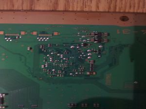
Syscon is the main power controller chip. It is responsible for powering up the various power systems and for configuring and initialising the CELL, RSX and | Syscon is the main power controller chip. It is responsible for powering up the various power systems and for configuring and initialising the [[CELL BE]], [[RSX]] and [[South Bridge]]. It communicates with these devices via seperate SPI busses. There is external access by JTAG (Which appears to have been disabled after factory programming) and Serial. | ||
= Serialnumbers @ SKU = | = Serialnumbers @ SKU = | ||
| Line 10: | Line 10: | ||
! [[SKU Models|Model]] !! [[IDPS|Type]] !! [[Motherboard Revisions|Board]] !! [[Syscon Hardware|Syscon<br />part no.]] !! [[More System Information#First_section|Soft<br />Id.]] !! Notes | ! [[SKU Models|Model]] !! [[IDPS|Type]] !! [[Motherboard Revisions|Board]] !! [[Syscon Hardware|Syscon<br />part no.]] !! [[More System Information#First_section|Soft<br />Id.]] !! Notes | ||
|- | |- | ||
| | | [[CECHAxx]] || 0x01 || [[COK-00x#COK-001|COK-001]] || CXR713120-201GB || 0B8E || | ||
|- | |- | ||
| | | [[CECHBxx]] || 0x02 || [[COK-00x#COK-001|COK-001]] || CXR713120-201GB || 0B8E || | ||
|- | |- | ||
| | | [[CECHCxx]] || 0x03 || [[COK-00x#COK-002|COK-002]] || CXR713120-201GB || 0C16 || | ||
|- | |- | ||
| style="background-color:lightgrey;" | <span style="background-color:lightgrey;"> | | style="background-color:lightgrey;" | <span style="background-color:lightgrey;">[[CECHDxx]]</span> || style="background-color:lightgrey;" | <span style="background-color:lightgrey;">-</span> || style="background-color:lightgrey;" | <span style="background-color:lightgrey;">-</span> || style="background-color:lightgrey;" | <span style="background-color:lightgrey;">-</span> || style="background-color:lightgrey;" | <span style="background-color:lightgrey;">-</span> || style="background-color:lightgrey;" | <span style="background-color:lightgrey;">-</span> | ||
|- | |- | ||
| | | [[CECHExx]] || 0x04 || [[COK-00x#COK-002|COK-002]]<br /> or<br />[[COK-00x#COK-002W|COK-002W]] || CXR713120-201GB || 0C16 || | ||
|- | |- | ||
| style="background-color:lightgrey;" | <span style="background-color:lightgrey;">CECHF</span> || style="background-color:lightgrey;" | <span style="background-color:lightgrey;">-</span> || style="background-color:lightgrey;" | <span style="background-color:lightgrey;">-</span> || style="background-color:lightgrey;" | <span style="background-color:lightgrey;">-</span> || style="background-color:lightgrey;" | <span style="background-color:lightgrey;">-</span> || style="background-color:lightgrey;" | <span style="background-color:lightgrey;">-</span> | | style="background-color:lightgrey;" | <span style="background-color:lightgrey;">CECHF</span> || style="background-color:lightgrey;" | <span style="background-color:lightgrey;">-</span> || style="background-color:lightgrey;" | <span style="background-color:lightgrey;">-</span> || style="background-color:lightgrey;" | <span style="background-color:lightgrey;">-</span> || style="background-color:lightgrey;" | <span style="background-color:lightgrey;">-</span> || style="background-color:lightgrey;" | <span style="background-color:lightgrey;">-</span> | ||
|- | |- | ||
| | | [[CECHGxx]] || 0x05 || [[SEM-00x|SEM-001]] || CXR713120-201GB || 0D52 || | ||
|- | |- | ||
| | | [[CECHHxx]] || 0x06 || [[DIA-00x#DIA-001|DIA-001]] || CXR713120-201GB || 0DBF || | ||
|- | |- | ||
| style="background-color:lightgrey;" | <span style="background-color:lightgrey;"> | | style="background-color:lightgrey;" | <span style="background-color:lightgrey;">[[CECHIxx]]</span> || style="background-color:lightgrey;" | <span style="background-color:lightgrey;">-</span> || style="background-color:lightgrey;" | <span style="background-color:lightgrey;">-</span> || style="background-color:lightgrey;" | <span style="background-color:lightgrey;">-</span> || style="background-color:lightgrey;" | <span style="background-color:lightgrey;">-</span> || style="background-color:lightgrey;" | <span style="background-color:lightgrey;">-</span> | ||
|- | |- | ||
| | | [[CECHJxx]] || 0x07 || [[DIA-00x#DIA-002|DIA-002]] || CXR713120-201GB || 0E69 || | ||
|- | |- | ||
| | | [[CECHKxx]] || 0x07 || [[DIA-00x#DIA-002|DIA-002]] || CXR713120-201GB || 0E69 || | ||
|- | |- | ||
| | | [[CECHLxx]] || 0x08 || [[VER-00x|VER-001]] || SW-301<br /> or<br />SW-302 || 065D || | ||
|- | |- | ||
| | | [[CECHMxx]] || 0x08 || [[VER-00x|VER-001]] || SW-301<br /> or<br />SW-302 || 065D || | ||
|- | |- | ||
| style="background-color:lightgrey;" | <span style="background-color:lightgrey;"> | | style="background-color:lightgrey;" | <span style="background-color:lightgrey;">[[CECHNxx]]</span> || style="background-color:lightgrey;" | <span style="background-color:lightgrey;">-</span> || style="background-color:lightgrey;" | <span style="background-color:lightgrey;">-</span> || style="background-color:lightgrey;" | <span style="background-color:lightgrey;">-</span> || style="background-color:lightgrey;" | <span style="background-color:lightgrey;">-</span> || style="background-color:lightgrey;" | <span style="background-color:lightgrey;">-</span> | ||
|- | |- | ||
| style="background-color:lightgrey;" | <span style="background-color:lightgrey;"> | | style="background-color:lightgrey;" | <span style="background-color:lightgrey;">[[CECHOxx]]</span> || style="background-color:lightgrey;" | <span style="background-color:lightgrey;">-</span> || style="background-color:lightgrey;" | <span style="background-color:lightgrey;">-</span> || style="background-color:lightgrey;" | <span style="background-color:lightgrey;">-</span> || style="background-color:lightgrey;" | <span style="background-color:lightgrey;">-</span> || style="background-color:lightgrey;" | <span style="background-color:lightgrey;">-</span> | ||
|- | |- | ||
| | | [[CECHPxx]] || 0x08 || [[VER-00x|VER-001]] || SW-301<br /> or<br />SW-302 || 065D || | ||
|- | |- | ||
| | | [[CECHQxx]] || 0x08 || [[VER-00x|VER-001]] || SW-301<br /> or<br />SW-302 || 065D || | ||
|- | |- | ||
| CECH- | | [[CECH-20xx]] || 0x09 || [[DYN-00x|DYN-001]] || SW2-301 || 0832 || | ||
|- | |- | ||
| CECH- | | [[CECH-21xx]] || 0x0A || [[SUR-00x|SUR-001]] || SW2-301 || 08C2 || | ||
|- | |- | ||
| CECH- | | [[CECH-25xx]] || 0x0B || [[JTP-00x|JTP-001]]<br /> or<br />[[JSD-00x|JSD-001]] || SW2-301 || 08C2 || | ||
|- | |- | ||
| CECH- | | [[CECH-30xx]] || 0x0B || [[KTE-00x|KTE-001]] || SW2-301 || 0918 || | ||
|- | |- | ||
|} | |} | ||
| Line 93: | Line 93: | ||
@ = VDD2, VDD1, VDD0 | @ = VDD2, VDD1, VDD0 | ||
</pre>[[File:SYSCON_GEN1.JPG|thumb|Syscon 1st Generation (BGA Packaging)]]</div> | </pre>[[File:SYSCON_GEN1.JPG|thumb|Syscon 1st Generation (BGA Packaging)]]</div> | ||
Early PS3 : up to including | Early PS3 : up to including [[CECHKxx]]/[[DIA-00x#DIA-002|DIA-002]] | ||
==== Pinout ==== | ==== Pinout ==== | ||
| Line 522: | Line 522: | ||
This points are availables to intercept signals by soldering wires, attaching probes, osciloscopes, etc... The photos are only orientatives to follow the traces, there's no need to remove the SYSCON to intercept this signals so can be done while its working | This points are availables to intercept signals by soldering wires, attaching probes, osciloscopes, etc... The photos are only orientatives to follow the traces, there's no need to remove the SYSCON to intercept this signals so can be done while its working | ||
All this points has been hardware reverse engineered from a CECHH02/DIA-001 motherboard | All this points has been hardware reverse engineered from a [[CECHHxx|CECHH02]]/[[DIA-00x#DIA-001|DIA-001]] motherboard | ||
===== Topside Pinout ===== | ===== Topside Pinout ===== | ||
<div style="float:right">[[File:syscon_top.jpg|thumbnail|Syscon Top Pinouts<br />CECHH02/DIA-001]]</div> | <div style="float:right">[[File:syscon_top.jpg|thumbnail|Syscon Top Pinouts<br />[[CECHHxx|CECHH02]]/[[DIA-00x#DIA-001|DIA-001]]]]</div> | ||
{|class="wikitable" | {|class="wikitable" | ||
| Line 586: | Line 586: | ||
===== Bottomside Pinout ===== | ===== Bottomside Pinout ===== | ||
<div style="float:right">[[File:syscon_bottom.jpg|thumbnail|Syscon Bottom Pinouts<br />CECHH02/DIA-001]]</div> | <div style="float:right">[[File:syscon_bottom.jpg|thumbnail|Syscon Bottom Pinouts<br />[[CECHHxx|CECHH02]]/[[DIA-00x#DIA-001|DIA-001]]]]</div> | ||
{|class="wikitable" | {|class="wikitable" | ||
| Line 686: | Line 686: | ||
===== CECHG01 Pictures - SEM-001 ===== | ===== CECHG01 Pictures - SEM-001 ===== | ||
====== Topside Pictures ====== | ====== Topside Pictures ====== | ||
<div style="float:right">[[File:syscon_top_cechg01.jpg|thumbnail|Syscon Top Pinouts<br />CECHG01/SEM-001]]</div> | <div style="float:right">[[File:syscon_top_cechg01.jpg|thumbnail|Syscon Top Pinouts<br />[[CECHGxx|CECHG01]]/[[SEM-00x|SEM-001]]]]</div> | ||
<br /><br /><br /><br /><br /><br /><br /><br /><br /> | <br /><br /><br /><br /><br /><br /><br /><br /><br /> | ||
====== Bottomside Pictures ====== | ====== Bottomside Pictures ====== | ||
<div style="float:right">[[File:syscon_bottom_cechg01.jpg|thumbnail|Syscon Bottom Pinouts<br />CECHG01/SEM-001]]</div> | <div style="float:right">[[File:syscon_bottom_cechg01.jpg|thumbnail|Syscon Bottom Pinouts<br />[[CECHGxx|CECHG01]]/[[SEM-00x|SEM-001]]]]</div> | ||
<br /><br /><br /><br /><br /><br /><br /><br /><br /> | <br /><br /><br /><br /><br /><br /><br /><br /><br /> | ||
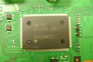
=== Generation 2: SW-301 === | === Generation 2: SW-301 === | ||
Newer generation Syscons are first to be seen on PS3 FAT CECHL/VER-001 board up to CECHQ/VER-001 | Newer generation Syscons are first to be seen on PS3 FAT [[CECHLxx|CECHL]]/[[VER-00x|VER-001]] board up to [[CECHQxx|CECHQ]]/[[VER-00x|VER-001]] | ||
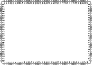
<div style="float:right">[[File:SYSCON_GEN2.JPG|thumb|Photo of a newer generation Syscon as seen on a CECHL VER-001 board<br />Syscon 'SW-301' 2nd Generation (QFP Packaging)]]<br /><br />[[File:Fp128b_pin_arrangement.png|thumb|QFP Package : 128 pins<br />Syscon 'SW-301' 2nd Generation<br />''pin 1 left bottom at mark, counter clockwise from south (pins 1-38) to east (pins 39-64), north (pins 65-102), west (103-128))'']]</div> | <div style="float:right">[[File:SYSCON_GEN2.JPG|thumb|Photo of a newer generation Syscon as seen on a[[CECHLxx|CECHL]]/[[VER-00x|VER-001]] board<br />Syscon 'SW-301' 2nd Generation (QFP Packaging)]]<br /><br />[[File:Fp128b_pin_arrangement.png|thumb|QFP Package : 128 pins<br />Syscon 'SW-301' 2nd Generation<br />''pin 1 left bottom at mark, counter clockwise from south (pins 1-38) to east (pins 39-64), north (pins 65-102), west (103-128))'']]</div> | ||
==== Pinout ==== | ==== Pinout ==== | ||
| Line 964: | Line 964: | ||
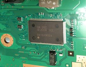
=== Generation 2-2: SW-302 === | === Generation 2-2: SW-302 === | ||
<div style="float:right">[[File:Syscon-sw302.jpg|thumb|Photo of rev2 subversion on CECHL<br />Syscon 'SW-302' 2-2nd Generation (QFP Packaging)]]<br /><br />[[File:Fp128b_pin_arrangement.png|thumb|QFP Package : 128 pins<br />Syscon 'SW-301' 2nd Generation<br />''pin 1 left bottom at mark, counter clockwise from south (pins 1-38) to east (pins 39-64), north (pins 65-102), west (103-128))'']]</div> | <div style="float:right">[[File:Syscon-sw302.jpg|thumb|Photo of rev2 subversion on [[CECHLxx|CECHL]]/[[VER-00x|VER-001]]<br />Syscon 'SW-302' 2-2nd Generation (QFP Packaging)]]<br /><br />[[File:Fp128b_pin_arrangement.png|thumb|QFP Package : 128 pins<br />Syscon 'SW-301' 2nd Generation<br />''pin 1 left bottom at mark, counter clockwise from south (pins 1-38) to east (pins 39-64), north (pins 65-102), west (103-128))'']]</div> | ||
Updated version as seen on CECHL | Updated version as seen on [[CECHLxx|CECHL]]/[[VER-00x|VER-001]] | ||
==== Pinout ==== | ==== Pinout ==== | ||
| Line 1,234: | Line 1,234: | ||
=== Generation 3: SW2-301 === | === Generation 3: SW2-301 === | ||
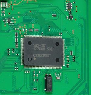
<div style="float:right">[[File:SW2-301 0920KMOOT-ps3slim.jpg|thumb|Uupdated subversion as seen on PS3 Slim<br />Syscon 'SW2-301' 3rd Generation (QFP Packaging)]]<br />[[File:Fp128b_pin_arrangement.png|thumb|QFP Package : 128 pins<br />Syscon 'SW-301' 2nd Generation<br />''pin 1 left bottom at mark, counter clockwise from south (pins 1-38) to east (pins 39-64), north (pins 65-102), west (103-128))'']]</div> | <div style="float:right">[[File:SW2-301 0920KMOOT-ps3slim.jpg|thumb|Uupdated subversion as seen on PS3 Slim<br />Syscon 'SW2-301' 3rd Generation (QFP Packaging)]]<br />[[File:Fp128b_pin_arrangement.png|thumb|QFP Package : 128 pins<br />Syscon 'SW-301' 2nd Generation<br />''pin 1 left bottom at mark, counter clockwise from south (pins 1-38) to east (pins 39-64), north (pins 65-102), west (103-128))'']]</div> | ||
Updated version (with the same pinout as SW-301) on the PS3 slim CECH- | Updated version (with the same pinout as SW-301) on the PS3 slim [[CECH-20xx]]/[[DYN-00x|DYN-001]] and later. | ||
==== Pinout ==== | ==== Pinout ==== | ||
| Line 1,544: | Line 1,544: | ||
NG F0000003:4E | NG F0000003:4E | ||
</pre> | </pre> | ||
{{Models}} | |||
[[Category:System Controller]] | |||
Revision as of 02:39, 26 March 2012
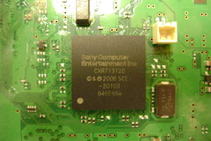
Syscon is the main power controller chip. It is responsible for powering up the various power systems and for configuring and initialising the CELL BE, RSX and South Bridge. It communicates with these devices via seperate SPI busses. There is external access by JTAG (Which appears to have been disabled after factory programming) and Serial.
Serialnumbers @ SKU
SoftID { 065D, 0832, 08A0, 08C2, 0918, 0B8E, 0C16, 0D52, 0DBF, 0E69, 0F29, 0F38 };
| Model | Type | Board | Syscon part no. |
Soft Id. |
Notes |
|---|---|---|---|---|---|
| CECHAxx | 0x01 | COK-001 | CXR713120-201GB | 0B8E | |
| CECHBxx | 0x02 | COK-001 | CXR713120-201GB | 0B8E | |
| CECHCxx | 0x03 | COK-002 | CXR713120-201GB | 0C16 | |
| CECHDxx | - | - | - | - | - |
| CECHExx | 0x04 | COK-002 or COK-002W |
CXR713120-201GB | 0C16 | |
| CECHF | - | - | - | - | - |
| CECHGxx | 0x05 | SEM-001 | CXR713120-201GB | 0D52 | |
| CECHHxx | 0x06 | DIA-001 | CXR713120-201GB | 0DBF | |
| CECHIxx | - | - | - | - | - |
| CECHJxx | 0x07 | DIA-002 | CXR713120-201GB | 0E69 | |
| CECHKxx | 0x07 | DIA-002 | CXR713120-201GB | 0E69 | |
| CECHLxx | 0x08 | VER-001 | SW-301 or SW-302 |
065D | |
| CECHMxx | 0x08 | VER-001 | SW-301 or SW-302 |
065D | |
| CECHNxx | - | - | - | - | - |
| CECHOxx | - | - | - | - | - |
| CECHPxx | 0x08 | VER-001 | SW-301 or SW-302 |
065D | |
| CECHQxx | 0x08 | VER-001 | SW-301 or SW-302 |
065D | |
| CECH-20xx | 0x09 | DYN-001 | SW2-301 | 0832 | |
| CECH-21xx | 0x0A | SUR-001 | SW2-301 | 08C2 | |
| CECH-25xx | 0x0B | JTP-001 or JSD-001 |
SW2-301 | 08C2 | |
| CECH-30xx | 0x0B | KTE-001 | SW2-301 | 0918 |
Pinouts
Retail
Generation 1: CXR713120-201GB
200 pin BGA package
Ball array, board orientated

    T R P N M L K J H G F E D C B A

 1    M M M M - N N N N N - O O +     1
 2  M M M M M @ N N N N N N @ - J J   2
 3  - @                         J J   3
 4  & -   A A N N N N O O O O   J J   4
 5  & +   A A N N N N O O O O   J J   5
 6  - -   A A + - + N - + H H   R R   6
 7  & #   A A * * # # - + H H   R R   7
 8  Q Q   G G * *     - + H H   K K   8
 9  Q Q   G G * *         H H   K K   9
10  Q Q   G G # # . + - + F F   K K  10
11  Q B   G G # - & & + ^ F F   K K  11
12  B B   C C C C D D D D F F   E E  12
13  B B   C C C C D D D D F F   E E  13
14  B B                         E E  14
15  B P P I I I $ . $ $ $ $ & - E E  15
16    P P I I I $ . $ $ $ $ & & &    16

    T R P N M L K J H G F E D C B A

Legend:
* = JTAG
  = N/C
& = Reset & Clock
$ = EEPROM Interface (U15, U16?? Perhaps J15 & J16)
- = Ground
+ = +3.3v
# = +1.8v (U10?? Perhaps J10)
^ = +battery
@ = VDD2, VDD1, VDD0
Early PS3 : up to including CECHKxx/DIA-002
Pinout
| Pin # | Name | Port | Description |
|---|---|---|---|
| T2 | /BE_INT | Port M Cell Control Line |
|
| R1 | PM7 | ||
| R2 | PM6 | ||
| P1 | BE_POWGOOD | ||
| P2 | /BE_RESET | ||
| N1 | BE_SPI_CLK | Cell SPI Bus | |
| N2 | BE_SPI_DO | ||
| M1 | BE_SPI_DI | ||
| M2 | /BE_SPI_CS | ||
| L4 | PL8 | Port N | unused |
| L5 | PL7 | ||
| K4 | PL6 | ||
| K5 | PL5 | ||
| J4 | PL4 | ||
| J5 | PL3 | ||
| H4 | PL2 | ||
| H5 | PL1 | ||
| H6 | PL0 | ||
| A8 | SB_SPI_CLK | Port K | Southbridge SPI Bus |
| B8 | SB_SPI_DO | ||
| A9 | SB_SPI_DI | ||
| B9 | /SB_SPI_CS | ||
| A10 | SEL2_I2C_SCL | ||
| B10 | SEL2_I2C_SDA | ||
| A11 | ACDC_STBY | ||
| B11 | PK0 | ||
| B5 | PJ7 | Port J | |
| A5 | DISC_OUT12_SW | ||
| B2 | DISC_OUT8_SW | ||
| A2 | DISC_IN | ||
| B3 | SW_10 | ||
| A3 | SW_0 | ||
| B4 | SW_8_B | ||
| A4 | SW_8_C | ||
| L16 | SW_PCI | Port I | |
| L15 | DISC_CHUCK | ||
| M16 | DISC_PHOT_LED | ||
| M15 | SW_2 | ||
| N16 | DIAG_MODE | ||
| N15 | BACKUP_MODE | ||
| E6 | /HDMI_INT | Port H | |
| D6 | VD_CECI0 | ||
| E7 | PH5 | ||
| D7 | /RS_POW_FAIL | ||
| E8 | /MUL_CHKSTP_IN | ||
| D8 | /MUL_TRG_IN | ||
| E9 | /SYS_THR_ALRT | ||
| D9 | /SB_INT | ||
| M11 | SW_ATA | Port G | |
| N11 | SW_4_A | ||
| M10 | /XDR_FET_VREF | ||
| N10 | /XDR_FET_SCK | ||
| M9 | BUZZER | ||
| N9 | SW_PWM | ||
| M8 | FANPWM1 | ||
| N8 | FANPWM0 | ||
| E10 | /MUL_CHKSTP_OUT | Port F | |
| D10 | /MUL_TAG_OUT | ||
| E11 | /SB_CGRESET | ||
| D11 | /SB_RESET | ||
| E12 | BT_WAKEON | ||
| D12 | BE_VCS_1.25_ON | ||
| E13 | BE_VCS_1.30_ON | ||
| D13 | SW_1A | ||
| A12 | /EJECT_SW | Port E | |
| B12 | /POW_SW | ||
| A13 | /SB_EBUS_RESET | ||
| B13 | SB_EBUS_BRDY | ||
| A14 | PE3 | ||
| B14 | VD_CECI1 | ||
| A15 | /BE_POW_FAIL | ||
| B15 | /POW_FAIL | ||
| F13 | SW_5_B | Port D | |
| F12 | MK_EN | ||
| G13 | BEVRM_VID5 | ||
| G12 | BEVRM_VID4 | ||
| H13 | BEVRM_VID3 | ||
| H12 | BEVRM_VID2 | ||
| J13 | BEVRM_VID1 | ||
| J12 | BEVRM_VID0 | ||
| K13 | SW_HDD | Port C | |
| K12 | I2CBUS_EN | ||
| L13 | RSXVRM_VID5 | ||
| L12 | RSXVRM_VID4 | ||
| M13 | RSXVRM_VID3 | ||
| M12 | RSXVRM_VID2 | ||
| N13 | RSXVRM_VID1 | ||
| N12 | RSXVRM_VID0 | ||
| T15 | SW_8_A | Port B | |
| R14 | SW_7_A | ||
| T14 | SW_6 | ||
| R13 | SW_1_B | ||
| T13 | SW_4_B | ||
| R12 | SW_3 | ||
| T12 | VD_CECO1 | ||
| R11 | VD_CECO0 | ||
| N7 | STBY_LED | Port A | |
| M7 | POW_LED | ||
| N6 | /AUDIO_MUTE | ||
| M6 | SW_7_B | ||
| N5 | /BT_RESET | ||
| M5 | /GBE_RESET | ||
| N4 | SW_5_A | ||
| M4 | SW_9 | ||
| U16 | RBB | EEPROM Interface | |
| K16 | PI7 | ||
| U15 | WCB | ||
| K15 | PI6 | ||
| E16 | SKB | ||
| E15 | PP3 | ||
| G16 | DI | ||
| G15 | PP2 | ||
| H16 | DO | ||
| H15 | PP1 | ||
| F16 | CSB | ||
| F15 | PP0 | ||
| H11 | TESTMODE | Reset & Clock | |
| B16 | OSCOUT | ||
| C16 | OSCIN | ||
| D16 | 32KOUT | ||
| D15 | 32KIN | ||
| T5 | EXTAL | ||
| T4 | XTAL | ||
| T7 | XXTALO | ||
| J11 | /RST | ||
| R4 | AVSUO | Power Port | Ground |
| R5 | AVDUO | +3.3v | |
| G6 | AVSS | Ground | |
| C2 | AVREF2 | Ground | |
| B1 | AVREF1 | +3.3v | |
| F7 | AVDD | +3.3v | |
| K11 | VSSF | Ground | |
| K6 | VSSF | Ground | |
| L6 | VDDF | +3.3v | |
| G7 | VSS | Ground | |
| G8 | |||
| G10 | |||
| T6 | |||
| R6 | |||
| T3 | |||
| L1 | |||
| E1 | |||
| C15 | VSSep | Ground | |
| G11 | VDDep | +3.3v | |
| F11 | VDDbat | +battery | |
| H7 | DVDD | +1.8v | |
| U10 | |||
| K10 | |||
| L10 | |||
| L11 | |||
| R7 | |||
| J7 | |||
| F8 | VDD3 | +3.3v | |
| F10 | |||
| H10 | |||
| J6 | |||
| F6 | |||
| D2 | VDD2 | +1.5V_RSX_VDDIO | |
| R3 | VDD1 | +1.2V_MC2_VDDIO | |
| L2 | VDD0 | +1.2V_MC2_VDDIO | |
| A16 | NC | ||
| T16 | |||
| T1 | |||
| A1 | |||
| G9 | |||
| F9 | |||
| L8 | JRTCK | JTAG Interface | |
| K8 | JTCK | ||
| K9 | JTDO | ||
| L9 | JTMS | ||
| K7 | JTDI | ||
| L7 | JNTAST | ||
| A6 | PR3 | Port R | |
| B6 | MC_P_OFF_REQ | ||
| A7 | MC_ALIVE | ||
| B7 | MC_RESERVED1 | ||
| R10 | RMC_IN | Port Q | |
| T11 | PQ5 | ||
| T10 | PQ4 | ||
| T8 | SEL2_IEC_SCL | ||
| T9 | SEL2_I2C_SDA | ||
| R9 | PQ1 | ||
| R8 | RSX_FBVDD_SEL | ||
| P16 | UART0_TxD | Port P | Serial Transmit |
| P15 | UART0_RxD | Serial Receive | |
| R16 | SEL1_I2C_SCL | ||
| R15 | SEL1_I2C_SDA | ||
| D1 | SEL0_I2C_SCL | Port O | |
| C1 | SEL0_I2C_SDA | ||
| G4 | PO7 | ||
| F4 | HDMI_RST0 | ||
| G5 | PO5 | ||
| F5 | DISC_IN_MECHA | ||
| E4 | EJECT_MECHA | ||
| D4 | /XDR_FET_RST | ||
| E5 | /GX_VSRST | ||
| D5 | XCG_EN | ||
| K2 | /VD_VINT1 | Port N | |
| K1 | /VD_VINT0 | ||
| J2 | /RSX_INT | ||
| J1 | RSX_FLDO | ||
| H2 | PN6 | ||
| H1 | PN5 | ||
| G2 | /RSX_RESET | ||
| G1 | RSX_SPI_CLK | RSX SPI Bus | |
| F2 | RSX_SPI_DO | ||
| F1 | RSX_SPI_DI | ||
| E2 | /RSX_SPI_CS | ||
Intercepting signals
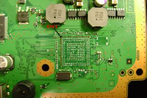
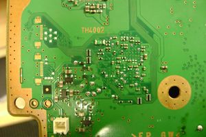
This points are availables to intercept signals by soldering wires, attaching probes, osciloscopes, etc... The photos are only orientatives to follow the traces, there's no need to remove the SYSCON to intercept this signals so can be done while its working
All this points has been hardware reverse engineered from a CECHH02/DIA-001 motherboard
Topside Pinout
| Pin # | Name | Description |
|---|---|---|
| B3 | SW_10 | Unknown |
| A6 | MC_RESERVED2 | Unknown |
| E10 | MUL_CHKSTP_OUT | Unknown |
| C15 | VSS | Power Ground |
| B16 | OSCOUT | Goes to unpopulated crystal |
| C16 | OSCIN | From unpupulated crystal |
| B15 | POW_FAIL | Power Failure Signal |
| H1 | PN5 | Unknown |
| H2 | PN6 | Unknown |
| R1 | PM7 | Unknown |
| R2 | PM6 | Unknown |
| M4 | SW9 | Unknown |
| M10 | XDR_FET_SCK | Unknown |
Bottomside Pinout
| Pin # | Name | Description |
|---|---|---|
| R5 | VDD | +3.3v |
| R7 | DVDD | +1.8v |
| C15 | VSS | Power Ground |
| N16 | DIAG_MODE | Unknown |
| N15 | BACKUP_MODE | Unknown |
| P16 | UART0_TxD | Serial |
| P15 | UART0_RxD | Serial |
| R9 | PQ1 | Unknown |
| B12 | POW_SW | Power Switch |
| A12 | EJECT_SW | Eject Switch |
| L7 | JNTAST | JTAG |
| L8 | JRTCK | JTAG |
| L9 | JTMS | JTAG |
| K7 | JTDI | JTAG |
| K8 | JTCK | JTAG |
| K9 | JTDO | JTAG |
| M6 | SW_7_B | Unknown |
| M8 | FANPWM1 | Unknown |
| E5 | GX_VSRT | Unknown |
| B5 | DVE_RST | Unknown |
| G4 | HDMI_RST1 | Unknown |
| D4 | XDR_FET_RST | Unknown |
Perimeter traces
CECHG01 Pictures - SEM-001
Topside Pictures
Bottomside Pictures
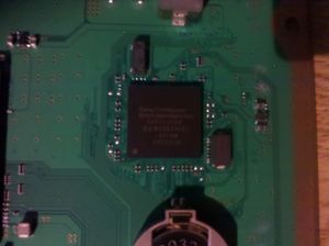
Generation 2: SW-301
Newer generation Syscons are first to be seen on PS3 FAT CECHL/VER-001 board up to CECHQ/VER-001
Pinout
| Pin # | Name | Port | Description |
|---|---|---|---|
| 0 | |||
| 1 | |||
| 2 | |||
| 3 | |||
| 4 | |||
| 5 | |||
| 6 | |||
| 7 | |||
| 8 | |||
| 9 | |||
| 10 | |||
| 11 | |||
| 12 | |||
| 13 | |||
| 14 | |||
| 15 | |||
| 16 | |||
| 17 | |||
| 18 | |||
| 19 | |||
| 20 | |||
| 21 | |||
| 22 | |||
| 23 | |||
| 24 | |||
| 25 | |||
| 26 | |||
| 27 | |||
| 28 | |||
| 29 | |||
| 30 | |||
| 31 | |||
| 32 | |||
| 33 | Ground | ||
| 34 | Ground | ||
| 35 | |||
| 36 | |||
| 37 | |||
| 38 | |||
| 39 | |||
| 40 | |||
| 41 | |||
| 42 | |||
| 43 | |||
| 44 | |||
| 45 | |||
| 46 | |||
| 47 | |||
| 48 | |||
| 49 | |||
| 50 | |||
| 51 | |||
| 52 | |||
| 53 | |||
| 54 | |||
| 55 | |||
| 56 | Ground | ||
| 57 | BUZZER | G | |
| 58 | |||
| 59 | |||
| 60 | |||
| 61 | |||
| 62 | |||
| 63 | |||
| 64 | |||
| 65 | |||
| 66 | |||
| 67 | |||
| 68 | |||
| 69 | |||
| 70 | |||
| 71 | |||
| 72 | |||
| 73 | |||
| 74 | |||
| 75 | |||
| 76 | |||
| 77 | |||
| 78 | |||
| 79 | |||
| 80 | |||
| 81 | |||
| 82 | |||
| 83 | |||
| 84 | |||
| 85 | |||
| 86 | |||
| 87 | |||
| 88 | |||
| 89 | |||
| 90 | |||
| 91 | |||
| 92 | |||
| 93 | |||
| 94 | |||
| 95 | |||
| 96 | |||
| 97 | |||
| 98 | |||
| 99 | |||
| 100 | |||
| 101 | Ground | ||
| 102 | |||
| 103 | |||
| 104 | |||
| 105 | |||
| 106 | |||
| 107 | |||
| 108 | |||
| 109 | |||
| 110 | |||
| 111 | |||
| 112 | |||
| 113 | |||
| 114 | |||
| 115 | |||
| 116 | |||
| 117 | |||
| 118 | |||
| 119 | |||
| 120 | |||
| 121 | |||
| 122 | |||
| 123 | |||
| 124 | |||
| 125 | |||
| 126 | FANPWM0 | G | Fan PWM Signal |
| 127 | |||
| 128 |
Generation 2-2: SW-302
Updated version as seen on CECHL/VER-001
Pinout
| Pin # | Name | Port | Description |
|---|---|---|---|
| 0 | |||
| 1 | |||
| 2 | |||
| 3 | |||
| 4 | |||
| 5 | |||
| 6 | |||
| 7 | |||
| 8 | |||
| 9 | |||
| 10 | |||
| 11 | |||
| 12 | |||
| 13 | |||
| 14 | |||
| 15 | |||
| 16 | |||
| 17 | |||
| 18 | |||
| 19 | |||
| 20 | |||
| 21 | |||
| 22 | |||
| 23 | |||
| 24 | |||
| 25 | |||
| 26 | |||
| 27 | |||
| 28 | |||
| 29 | |||
| 30 | |||
| 31 | |||
| 32 | |||
| 33 | Ground | ||
| 34 | Ground | ||
| 35 | |||
| 36 | |||
| 37 | |||
| 38 | |||
| 39 | |||
| 40 | |||
| 41 | |||
| 42 | |||
| 43 | |||
| 44 | |||
| 45 | |||
| 46 | |||
| 47 | |||
| 48 | |||
| 49 | |||
| 50 | |||
| 51 | |||
| 52 | |||
| 53 | |||
| 54 | |||
| 55 | |||
| 56 | Ground | ||
| 57 | (buzzer on 126 now) | ||
| 58 | |||
| 59 | |||
| 60 | |||
| 61 | |||
| 62 | |||
| 63 | |||
| 64 | |||
| 65 | |||
| 66 | |||
| 67 | |||
| 68 | |||
| 69 | |||
| 70 | |||
| 71 | |||
| 72 | |||
| 73 | |||
| 74 | |||
| 75 | |||
| 76 | |||
| 77 | |||
| 78 | |||
| 79 | |||
| 80 | |||
| 81 | |||
| 82 | |||
| 83 | |||
| 84 | |||
| 85 | |||
| 86 | |||
| 87 | |||
| 88 | |||
| 89 | |||
| 90 | |||
| 91 | |||
| 92 | |||
| 93 | |||
| 94 | |||
| 95 | |||
| 96 | |||
| 97 | |||
| 98 | |||
| 99 | |||
| 100 | |||
| 101 | Ground | ||
| 102 | |||
| 103 | |||
| 104 | |||
| 105 | |||
| 106 | |||
| 107 | |||
| 108 | |||
| 109 | |||
| 110 | |||
| 111 | |||
| 112 | |||
| 113 | |||
| 114 | |||
| 115 | |||
| 116 | |||
| 117 | |||
| 118 | |||
| 119 | |||
| 120 | |||
| 121 | |||
| 122 | |||
| 123 | |||
| 124 | |||
| 125 | |||
| 126 | Buzzer | ||
| 127 | |||
| 128 |
Generation 3: SW2-301
Updated version (with the same pinout as SW-301) on the PS3 slim CECH-20xx/DYN-001 and later.
Pinout
| Pin # | Name | Port | Description |
|---|---|---|---|
| 0 | |||
| 1 | |||
| 2 | |||
| 3 | |||
| 4 | |||
| 5 | |||
| 6 | |||
| 7 | |||
| 8 | |||
| 9 | |||
| 10 | |||
| 11 | |||
| 12 | |||
| 13 | |||
| 14 | |||
| 15 | |||
| 16 | |||
| 17 | |||
| 18 | |||
| 19 | |||
| 20 | |||
| 21 | |||
| 22 | |||
| 23 | |||
| 24 | |||
| 25 | |||
| 26 | |||
| 27 | |||
| 28 | |||
| 29 | |||
| 30 | |||
| 31 | |||
| 32 | |||
| 33 | Ground | ||
| 34 | Ground | ||
| 35 | |||
| 36 | |||
| 37 | |||
| 38 | |||
| 39 | |||
| 40 | |||
| 41 | |||
| 42 | |||
| 43 | |||
| 44 | |||
| 45 | |||
| 46 | |||
| 47 | |||
| 48 | |||
| 49 | |||
| 50 | |||
| 51 | |||
| 52 | |||
| 53 | |||
| 54 | |||
| 55 | |||
| 56 | Ground | ||
| 57 | BUZZER | G | |
| 58 | |||
| 59 | |||
| 60 | |||
| 61 | |||
| 62 | |||
| 63 | |||
| 64 | |||
| 65 | |||
| 66 | |||
| 67 | |||
| 68 | |||
| 69 | |||
| 70 | |||
| 71 | |||
| 72 | |||
| 73 | |||
| 74 | |||
| 75 | |||
| 76 | |||
| 77 | |||
| 78 | |||
| 79 | |||
| 80 | |||
| 81 | |||
| 82 | |||
| 83 | |||
| 84 | |||
| 85 | |||
| 86 | |||
| 87 | |||
| 88 | |||
| 89 | |||
| 90 | |||
| 91 | |||
| 92 | |||
| 93 | |||
| 94 | |||
| 95 | |||
| 96 | |||
| 97 | |||
| 98 | |||
| 99 | |||
| 100 | |||
| 101 | Ground | ||
| 102 | |||
| 103 | |||
| 104 | |||
| 105 | |||
| 106 | |||
| 107 | |||
| 108 | |||
| 109 | |||
| 110 | |||
| 111 | |||
| 112 | |||
| 113 | |||
| 114 | |||
| 115 | |||
| 116 | |||
| 117 | |||
| 118 | |||
| 119 | |||
| 120 | |||
| 121 | |||
| 122 | |||
| 123 | |||
| 124 | |||
| 125 | |||
| 126 | FANPWM0 | G | Fan PWM Signal |
| 127 | |||
| 128 |
Nonretail
CXR713F120A
Located on the Communication Processor Board in Reference Tool DECR1000A
JTAG/SPI/UART is not disabled on this models. Pinout should be fairly the same as retail CXR713120-201GB.
Syscon UART
You can attach a 3.3v TTL cable (LV-TTL) to the UART on syscon. There is a simple plaintext protocol involved. This varies on different syscon models. Example:
<command>:<hash>
Where the hash is the sum of command bytes & 0xFF
you should terminate commands with \r\n, the syscon messages are only terminated with \n
Here are some of the commands/messages encountered:
Messages:
Power applied (standby mode)
OK 00000000:3A

Power on
# (PowerOn State):7F

Power off (Hard shutdown)
# (PowerOff State):DD

After Fan test:
# (PowerOff State) (Fatal):36

No text, invalid hash:
NG F0000002:4D

Commands:
VER:ED
OK 00000000 S1E 00 00 065D:A4

ERRLOG:CB
OK 00000000:3A

DATE:1E
NG F0000003:4E
