Service Connectors: Difference between revisions
Jump to navigation
Jump to search
m (→1st Generation) |
|||
| Line 120: | Line 120: | ||
|- | |- | ||
|}<br /><br /> | |}<br /><br /> | ||
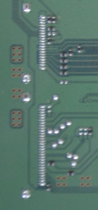
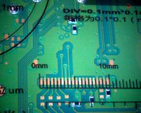
<div style="float:right">[[File:APU-Service_Connectors.png|200px|thumb|left|[[DUH-D1000xA_series]][[CVN-001]] img1]]<br/> </div> | |||
{| border="1" cellspacing="0" cellpadding="5" border="#999" class="wikitable" style="border:1px solid #999; border-collapse: collapse;" | |||
|- bgcolor="#cccccc" | |||
! Pin !! Name !! Description | |||
|- | |||
| 1 || || | |||
|- | |||
| 2 || || | |||
|- | |||
| 3 || || | |||
|- | |||
| 4 || || | |||
|- | |||
| 5 || || | |||
|- | |||
| 6 || || | |||
|- | |||
| 7 || || | |||
|- | |||
| 8 || || | |||
|- | |||
| 9 || || | |||
|- | |||
| 10 || || | |||
|- | |||
| 11 || || | |||
|- | |||
| 12 || || | |||
|- | |||
| 13 || || | |||
|- | |||
| 14 || || | |||
|- | |||
| 15 || || | |||
|- | |||
| 16 || || | |||
|- | |||
| 17 || || | |||
|- | |||
| 18 || || | |||
|- | |||
| 19 || || | |||
|- | |||
| 20 || || | |||
|- | |||
| 21 || || | |||
|- | |||
| 22 || || | |||
|- | |||
| 23 || || | |||
|- | |||
| 24 || || | |||
|- | |||
| 25 || || | |||
|- | |||
| 26 || || | |||
|- | |||
| 27 || || | |||
|- | |||
| 28 || || | |||
|- | |||
| 29 || || | |||
|- | |||
| 30 || || | |||
|- | |||
| 31 || || | |||
|- | |||
| 32 || || | |||
|- | |||
|} | |||
==1st Generation== | ==1st Generation== | ||
Revision as of 17:06, 16 September 2018
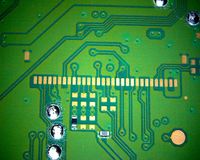
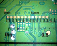
JTAG/UART/SPI/Diagnostic I/O used in Sony repair centers if a PS4 couldn't be fixed by software.
Preproduction Generation
| Pin | Name | Description |
|---|---|---|
| 1 | ||
| 2 | ||
| 3 | ||
| 4 | ||
| 5 | ||
| 6 | ||
| 7 | ||
| 8 | ||
| 9 | ||
| 10 | ||
| 11 | ||
| 12 | ||
| 13 | ||
| 14 | ||
| 15 | ||
| 16 | ||
| 17 | ||
| 18 | ||
| 19 | ||
| 20 | ||
| 21 | ||
| 22 | ||
| 23 | ||
| 24 | ||
| 25 | ||
| 26 | ||
| 27 | ||
| 28 | ||
| 29 | ||
| 30 | ||
| 31 | ||
| 32 |
| Pin | Name | Description |
|---|---|---|
| 1 | ||
| 2 | ||
| 3 | ||
| 4 | ||
| 5 | ||
| 6 | ||
| 7 | ||
| 8 | ||
| 9 | ||
| 10 | ||
| 11 | ||
| 12 | ||
| 13 | ||
| 14 | ||
| 15 | ||
| 16 | ||
| 17 | ||
| 18 | ||
| 19 | ||
| 20 |
| Pin | Name | Description |
|---|---|---|
| 1 | ||
| 2 | ||
| 3 | ||
| 4 | ||
| 5 | ||
| 6 | ||
| 7 | ||
| 8 | ||
| 9 | ||
| 10 | ||
| 11 | ||
| 12 | ||
| 13 | ||
| 14 | ||
| 15 | ||
| 16 | ||
| 17 | ||
| 18 | ||
| 19 | ||
| 20 | ||
| 21 | ||
| 22 | ||
| 23 | ||
| 24 | ||
| 25 | ||
| 26 | ||
| 27 | ||
| 28 | ||
| 29 | ||
| 30 | ||
| 31 | ||
| 32 |
1st Generation
| Pin | Name | Description |
|---|---|---|
| 1 | ||
| 2 | ||
| 3 | ||
| 4 | ||
| 5 | ||
| 6 | Gnd | Internal ground |
| 7 | I2C | I2C bus (100 kHz clock) |
| 8 | Gnd | Internal ground |
| 9 | ||
| 10 | ||
| 11 | ||
| 12 | ||
| 13 | Gnd | Internal ground |
| 14 | ||
| 15 | ||
| 16 | ||
| 17 | Gnd | Internal ground |
| 18 | ||
| 19 | ||
| 20 | ||
| 21 | ||
| 22 | Gnd | Internal ground |
| 23 | ||
| 24 | ||
| 25 | Gnd | Internal ground |
| 26 | ||
| 27 | ||
| 28 | ||
| 29 | ||
| 30 |
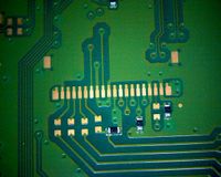
Aeolia debug (No activity was detected so far. It looks to be disabled / turned off)
| Pin | Name | Description |
|---|---|---|
| 1 | ||
| 2 | Gnd | Internal ground |
| 3 | ||
| 4 | ||
| 5 | ||
| 6 | ||
| 7 | ||
| 8 | Gnd | Internal ground |
| 9 | ||
| 10 | Gnd | Internal ground |
| 11 | 3.3V when console is started | |
| 12 | ||
| 13 | ||
| 14 | ||
| 15 | ||
| 16 | ||
| 17 | Gnd | Internal ground |
| 18 | ||
| 19 | Gnd | Internal ground |
| 20 | Vcc | +3.3V_STBY power (always on, including the deep standby) |
2nd Generation
- TODO
