Wifi
Wireless Networking
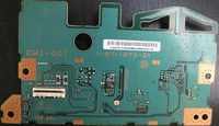
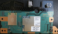
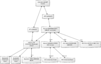
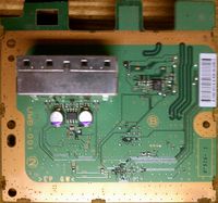
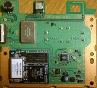
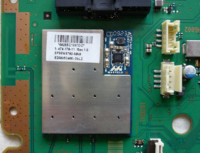
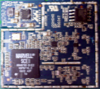
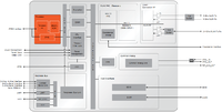
The PS3 contains two wireless technologies, Wi-Fi 802.11b/g and Bluetooth 2.0. It is not possible for both to be used at the same time, so the PS3 alternates between Wi-Fi and Bluetooth communication at a very fast frequency using time division multiplexing (note, see:Marvell-WiFi-Bluetooth-Coexistence.pdf). Both wireless capabilities are powered by the Marvell 88W8580 chip, used on both daughterboards CWI-001 (CECHA, CECHB, CECHC) and UWB-001 (CECHH, CECHJ, CECHK). In SKU Models CECHL and later, this wireless module updated with Marvell 88W8780 and became part of the motherboard (no longer on a separate daughterboard).
Hardware
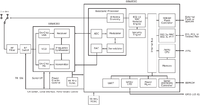
IEEE 802.11b/g wireless network and BlueTooth 2.0 EDR controller chip: Marvell 88W8580 / Marvell 88W8780. See: Bluetooth
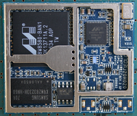
The Wi-Fi module uses two internal antennas and allows the PS3 to communicate with access points (normal mode) and Wi-Fi devices like the Sony PSP (AP mode for Remote Play). The Wi-Fi module contains a 16MB ISSI SDRAM memory chip, and a 64KB SPI Serial Interface NOR Macronix flash chip.
| Type | Size | Speed | Voltage | Packaging | Manufacturer | Serialnumber | Description |
|---|---|---|---|---|---|---|---|
| ARMv5TE-compliant | ?8kbit EEPROM? | 50MHz | ?3.3V? | 256-ball BGA | Marvell | 88W8580-BAN1 | PS3 Fat Wi-Fi controller chip |
| ARMv5TE-compliant | ?8kbit EEPROM? | ?50MHz? | ?3.3V? | ?256-ball BGA? | Marvell | 88W8780-BIE2 | PS3 Slim Wi-Fi controller chip |
| NOR Flash | 64KB | 85MHz | 3V | 8-pin | Macronix | MX25L512MC-12G | PS3 Fat Wi-Fi firmware chip |
| NOR Flash | 4Mbit | 85MHz | 3V | 8-pin | Macronix | MX25L4005AM2I-12G | PS3 Slim Wi-Fi firmware chip |
| SDRAM | 16MB | 166MHz, 6ns | 3.3V | 90-ball | ISSI | IS42S32400B-6BL | PS3 Wi-Fi working memory chip |
| SDRAM | 16MB (8Mx16) | 166MHz, 6ns CAS3 | 3.3V | 400mil 54-PIN TSOP-II | Nanya | NT5SV8M16FS-6K | PS3 Wi-Fi working memory chip (CECHJ and later models) |
Seperate Wifi/BT boards on PS3 Fat
CWI-001
part no. 1-871-870-21, CWI-001 (CECHA, CECHB, CECHC)
part no. 1-871-870-31, CWI-001 (CECHE)
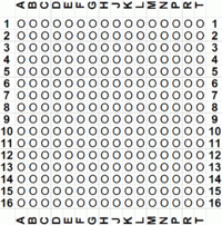
Marvell 88W8580-BAN1 (Wifi/Bluetooth controller)
Datasheet: -
Product Flyer: 88W8500-ProductFlyer.pdf (154.81 KB)
| A | B | C | D | E | F | G | J | K | L | M | N | P | R | T | |
| 1 | |||||||||||||||
| 2 | |||||||||||||||
| 3 | |||||||||||||||
| 4 | |||||||||||||||
| 5 | |||||||||||||||
| 6 | |||||||||||||||
| 7 | |||||||||||||||
| 8 | |||||||||||||||
| 9 | |||||||||||||||
| 10 | |||||||||||||||
| 11 | |||||||||||||||
| 12 | |||||||||||||||
| 13 | |||||||||||||||
| 14 | |||||||||||||||
| 15 | |||||||||||||||
| 16 | |||||||||||||||
| A | B | C | D | E | F | G | J | K | L | M | N | P | R | T |
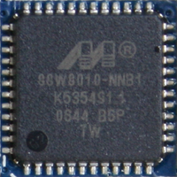
Marvell 88W8010-NNB1 (Wifi driver)
Package: TSOP-48
Macronix MX25L512MC-12G (Flash)
Datasheet: Macronix_MX25L512MC-12G.pdf (1.87 MB)
| Pad # | Name | Description |
|---|---|---|
| 1 | CS# | Chip Select |
| 2 | SO | Serial Data Output |
| 3 | WP# | Write Protection |
| 4 | GND | Ground |
| 5 | SI | Serial Data Input |
| 6 | SCLK | Clock Input |
| 7 | HOLD# | Hold, to pause the device without deselecting the device |
| 8 | VCC | +3.3V Power Supply |
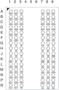
ISSI IS42S32400B-6BL (DRAM)
Datasheet: ISSI_IS42S32400B-6BL.pdf (675.22 KB)
| Pad # | Description |
|---|---|
| A0-A11 | Row Address Input |
| A0-A7 | Column Address Input |
| BA0, BA1 | Bank Select Address |
| DQ0 to DQ31 | Data I/O |
| CLK | System Clock Input |
| CKE | Clock Enable |
| CS | Chip Select |
| RAS | Row Address Strobe Command |
| CAS | Column Address Strobe Command |
| WE | Write Enable |
| DQM0-DQM3 | x32 Input/Output Mask |
| VDD | Power |
| Vss | Ground |
| VDDQ | Power Supply for I/O Pin |
| VssQ | Ground for I/O Pin |
| NC | No Connection |
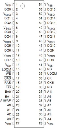
Nanya NT5SV8M16FS-6K (DRAM)
Datasheet: Nanya NT5SV8M16FS-6K (128 Mbit, 16 MB) : NTC-SDR-128M-F-R13.pdf
| Pin # | Description |
|---|---|
| CK | Clock Input |
| CKE (CKE0, CKE1) | Clock Enable |
| CS | Chip Select |
| RAS | Row Address Strobe |
| CAS | Column Address Strobe |
| WE | Write Enable |
| BA1, BA0 | Bank Select |
| A0 - A11 | Address Inputs |
| DQ0-DQ15 | Data Input/Output |
| DQM, LDQM, UDQM | Data Mask |
| VDD | Power (+3.3V) |
| VSS | Ground |
| VDDQ | Power for DQs (+3.3V) |
| VSSQ | Ground for DQs |
| NC | No Connection |
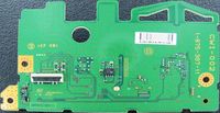
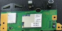
CWI-002
part no. 1-875-387-11, CWI-002 (CECHG)
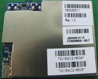
UWB-001
part no. 1-875-939-21, UWB-001 (CECHH, CECHJ, CECHK)
Marvell 88W8580-BAN1 (Wifi/Bluetooth controller)
Wifi#Marvell_88W8580-BAN1_.28Wifi.2FBluetooth_controller.29
Nanya NT5SV8M16FS-6K (DRAM)
Wifi#Nanya_NT5SV8M16FS-6K_.28DRAM.29
1-802-252-21 Rev 2.0 driver
No pics from inside (yet), please add if possible.
Sony CXN1502-3AAL 752D34S (BT driver subboard on UWB-001)
Bluetooth#Sony_CXN1502-3AAL_752D34S_.28BT_driver_subboard_on_UWB-001.29
Genesys GL852 (USB Hub)
see USB
Integrated Wifi/BT boards on PS3 FAT
Seen on: CECHL, CECHP
Circuit/design simulair to UWB-001, but implemented on the main L shaped board.
Integrated Wifi/BT boards on PS3 Slim
Marvell 88W8780-BIE2 (Wifi/BT controller)
Datasheet: -
Product Flyer: -
| A | B | C | D | E | F | G | J | K | L | M | N | P | R | T | |
| 1 | |||||||||||||||
| 2 | |||||||||||||||
| 3 | |||||||||||||||
| 4 | |||||||||||||||
| 5 | |||||||||||||||
| 6 | |||||||||||||||
| 7 | |||||||||||||||
| 8 | |||||||||||||||
| 9 | |||||||||||||||
| 10 | |||||||||||||||
| 11 | |||||||||||||||
| 12 | |||||||||||||||
| 13 | |||||||||||||||
| 14 | |||||||||||||||
| 15 | |||||||||||||||
| 16 | |||||||||||||||
| A | B | C | D | E | F | G | J | K | L | M | N | P | R | T |
Macronix MX25L4005AM2I-12G (Flash)
Datasheet: Macronix_MX25L4005AM2I-12G.pdf (1.5 MB)
| Pad # | Name | Description |
|---|---|---|
| 1 | CS# | Chip Select |
| 2 | SO | Serial Data Output |
| 3 | WP# | Write Protection |
| 4 | GND | Ground |
| 5 | SI | Serial Data Input |
| 6 | SCLK | Clock Input |
| 7 | HOLD# | Hold, to pause the device without deselecting the device |
| 8 | VCC | +3.3V Power Supply |

