Serial Adapter
The PSP's headphone remote (HPRM) port contains a connection to UART4 in order to implement rewind, fast forward, and play / pause. This connector is often repurposed for debugging.
Below are the HPRM pinouts for various PSP models along with instructions on how to build your own HPRM to serial adapter.
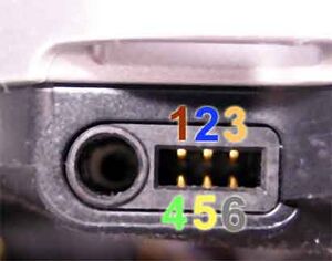
PSP-1000
This was originally documented by Marcus Comstedt More information on the HPRM serial protocol can be found on his page.
The PSP-1000's HPRM port operates at 2.5v
| Pin | Signal | Notes |
|---|---|---|
| 1 | Mic input | microphone signal, decouple with a capacitor to audio ground when using (sleeve of 3.5mm connector) |
| 2 | GND | Digital ground |
| 3 | UART4 TXD | PSP UART4 transmit |
| 4 | nWakeup | Ground this pin to wake PSP from standby |
| 5 | VCC_2v5 | 2.5v supply |
| 6 | UART4 RXD | PSP UART4 receive |
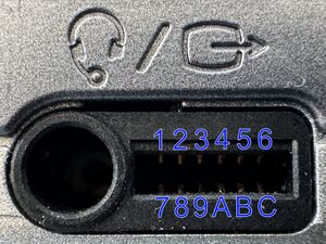
PSP-2000 & PSP-3000
PSP-2000 and PSP-3000's HPRM port is expanded to also carry video out signals. Serial signals operate at 1.9v on these models.
| Pin | Signal | Notes |
|---|---|---|
| 1 | Mic input | |
| 2 | UART4 TXD | PSP UART4 transmit |
| 3 | DGND | Digital ground |
| 4 | Y | Luma component video signal (green jack) |
| 5 | VGND | Video ground |
| 6 | Pr | Red / Luma difference component video signal (red jack) |
| 7 | UART4 RXD | PSP UART4 recieve |
| 8 | VCC_1v9 | 1.9v supply |
| 9 | Video Det | Video detect, 42k resistor to GND signals a composite cable |
| A | nWakeup | Ground this pin to wake PSP from standby |
| B | Pb | Blue / Lume difference component video signal (blue jack) |
| C | VGND | Video ground |
Making a cable
In these modern days, few people have a true 12v RS232 interface anymore on their computer - many developers prefer to use USB to Serial adapters as they are much easier to interface without the need for level translator ICs as in previous designs.
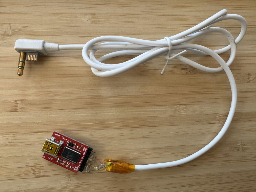
FT232RL adapter boards such as this or this may be easily adapted by removing the 3.3v/5v jumper and soldering the VCC (sometimes labeled 3v3) pin on the end header to the VCC_2v5 or VCC_1v9 pin on the HPRM port to provide the proper voltage reference for RX and TX signals.
Some FT232RL adapter boards will have 3.3v / 5v solder bridge pads on the back of the board, in this case you'll need to cut the trace connecting to default voltage to the FT232RL voltage reference pin in order to use the PSP's voltage reference instead of removing a jumper.
In all, four wires should be soldered from the HPRM cable to the FT232RL adapter: RX, TX, VCC_1v9, and DGND as in the photo below. Be sure to connect PSP RX to FT232RL TX and PSP TX to FT232RL RX!
Please note that wire colors will not be the same from cable to cable, especially with third party cables
NOTE: the 3.3v / 5v voltage jumper on the FT232RL board MUST be removed or else damage to your PSP will occur!
Click image to access higher resolution image.


