Serial Adapter: Difference between revisions
Jump to navigation
Jump to search
(Serial WIP) |
(Finish PSP-2000 / 3000 HPRM connector pinout) |
||
| Line 40: | Line 40: | ||
== PSP-2000 & PSP-3000 == | == PSP-2000 & PSP-3000 == | ||
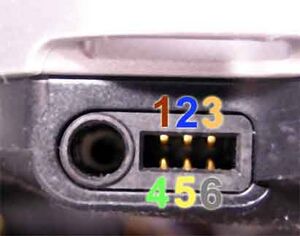
PSP-2000 and PSP-3000's HPRM port is expanded to also carry video out signals. | PSP-2000 and PSP-3000's HPRM port is expanded to also carry video out signals. Serial signals operate at 1.9v on these models. | ||
[[File:PSP-2000 Headphone remote port.jpg|alt=An image of the PSP-2000 headphone remote port with numbered pins|left|thumb|PSP-2000 HPRM port]] | [[File:PSP-2000 Headphone remote port.jpg|alt=An image of the PSP-2000 headphone remote port with numbered pins|left|thumb|PSP-2000 HPRM port]] | ||
{| class="wikitable" | {| class="wikitable" | ||
| Line 47: | Line 47: | ||
!Signal | !Signal | ||
!Notes | !Notes | ||
|- | |- | ||
|1 | |1 | ||
|Mic input | |Mic input | ||
| | | | ||
|- | |- | ||
|2 | |2 | ||
|UART4 TXD | |UART4 TXD | ||
| | |PSP UART4 transmit | ||
|- | |- | ||
|3 | |3 | ||
| | |DGND | ||
| | |Digital ground | ||
|- | |- | ||
|4 | |4 | ||
| | |Y | ||
| | |Luma component video signal (green jack) | ||
|- | |- | ||
|5 | |5 | ||
| | |VGND | ||
| | |Video ground | ||
|- | |- | ||
|6 | |6 | ||
| | |Pr | ||
| | |Red / Luma difference component video signal (red jack) | ||
|- | |- | ||
|7 | |7 | ||
| | |UART4 RXD | ||
| | |PSP UART4 recieve | ||
|- | |- | ||
|8 | |8 | ||
| | |VCC_1v9 | ||
| | |1.9v supply | ||
|- | |- | ||
|9 | |9 | ||
| | |Video Det | ||
| | |Video detect, 42k resistor to GND signals a composite cable | ||
|- | |- | ||
|A | |A | ||
| | |nWakeup | ||
| | |Ground this pin to wake PSP from standby | ||
|- | |- | ||
|B | |B | ||
| | |Pb | ||
| | |Blue / Lume difference component video signal (blue jack) | ||
|- | |- | ||
|C | |C | ||
| | |VGND | ||
| | |Video ground | ||
|} | |} | ||
Revision as of 21:42, 5 June 2024
The PSP's headphone remote (HPRM) port contains a connection to UART4 in order to implement rewind, fast forward, and play / pause. This connector is often repurposed for debugging.
Below are the HPRM pinouts for various PSP models along with instructions on how to build your own HPRM to serial adapter.
PSP-1000
This was originally documented by Marcus Comstedt More information on the HPRM serial protocol can be found on his page.
The PSP-1000's HPRM port operates at 2.5v

| Pin | Signal | Notes |
|---|---|---|
| 1 | Mic input | microphone signal, decouple with a capacitor to audio ground when using (sleeve of 3.5mm connector) |
| 2 | GND | Digital ground |
| 3 | UART4 TXD | PSP UART4 transmit |
| 4 | nWakeup | Ground this pin to wake PSP from standby |
| 5 | VCC_2v5 | 2.5v supply |
| 6 | UART4 RXD | PSP UART4 receive |
PSP-2000 & PSP-3000
PSP-2000 and PSP-3000's HPRM port is expanded to also carry video out signals. Serial signals operate at 1.9v on these models.

| Pin | Signal | Notes |
|---|---|---|
| 1 | Mic input | |
| 2 | UART4 TXD | PSP UART4 transmit |
| 3 | DGND | Digital ground |
| 4 | Y | Luma component video signal (green jack) |
| 5 | VGND | Video ground |
| 6 | Pr | Red / Luma difference component video signal (red jack) |
| 7 | UART4 RXD | PSP UART4 recieve |
| 8 | VCC_1v9 | 1.9v supply |
| 9 | Video Det | Video detect, 42k resistor to GND signals a composite cable |
| A | nWakeup | Ground this pin to wake PSP from standby |
| B | Pb | Blue / Lume difference component video signal (blue jack) |
| C | VGND | Video ground |