Service Connectors: Difference between revisions
Jump to navigation
Jump to search
(Added a comment on the 5pin connector. The unknown 2 pins connect to SSD controller IC.) |
(→5 Pins) |
||
| (8 intermediate revisions by the same user not shown) | |||
| Line 27: | Line 27: | ||
{| class="wikitable sortable" | {| class="wikitable sortable" | ||
|- | |- | ||
! PIN | ! PIN # (24 PIN#) !! Meaning !! Notes | ||
|- | |- | ||
| | | 1 || Ground || Ground Plane | ||
|- | |- | ||
| | | 2(7) || Transmit EMC || Used to send commands to EMC. command always <com>:<chk>\r\n | ||
|- | |- | ||
| | | 3(6) || Receive EMC || Used to recv responses from EMC. response always <res>:<chk>\r\n | ||
|- | |- | ||
| | | 4(14) || titania uart1 tx || titania uart1 tx (bootrom: 460800, eap fw, apu: 230400) | ||
|- | |- | ||
| | | 5(13) || titania uart1 rx || titania uart1 rx (bootrom: 460800, eap fw, apu: 230400) | ||
|- | |- | ||
|} | |} | ||
== 24 Pins == | == 24 Pins == | ||
* Major credits to shuffle2 for the complete pinout | |||
{| class="wikitable sortable" | {| class="wikitable sortable" | ||
! PIN | ! PIN # !! Meaning !! Notes | ||
|- | |- | ||
| | | 1 || VDD || 5v | ||
|- | |- | ||
| | | 2 || VDD || 5v | ||
|- | |- | ||
| | | 3 || GND || Ground Plane | ||
|- | |- | ||
| | | 4 || GND || Ground Plane | ||
|- | |- | ||
| | | 5 || emc gpio a1 || pulling low at emc boot causes emc rom to enter uart shell @ 460800 | ||
|- | |- | ||
| | | 6 || Receive EMC || Used to recv responses from EMC. response always <res>:<chk>\r\n (uart rx emc 115200) | ||
|- | |- | ||
| | | 7 || Transmit EMC || Used to send commands to EMC. command always <com>:<chk>\r\n (uart tx emc 115200) | ||
|- | |- | ||
| | | 8 || 3v3 || goes low when emc resets | ||
|- | |- | ||
| | | 9 || 0v || 0v | ||
|- | |- | ||
| | | 10 || GND || Ground Plane | ||
|- | |- | ||
| | | 11 || titania uart0 tx || titania uart0 tx (efc fw: 460800) | ||
|- | |- | ||
| | | 12 || titania uart0 rx || titania uart0 rx (efc fw: 460800) | ||
|- | |- | ||
| | | 13 || titania uart1 rx || titania uart1 rx (bootrom: 460800, eap fw, apu: 230400) | ||
|- | |- | ||
| | | 14 || titania uart1 tx || titania uart1 tx (bootrom: 460800, eap fw, apu: 230400) | ||
|- | |- | ||
| | | 15 || GND || Ground Plane | ||
|- | |- | ||
| | | 16 || emc gpio c5 || ("GPI SW" (only used if devif_det# active)) | ||
|- | |- | ||
| | | 17 || 0v || 0v | ||
|- | |- | ||
| | | 18 || 5v || 5v | ||
|- | |- | ||
| | | 19 || emc gpio a49 || emc gpio a49 | ||
|- | |- | ||
| | | 20 || emc gpio a27 || emc gpio a27. main power switch | ||
|- | |- | ||
| | | 21 || i2c data || i2c data (i2c_bus_4) | ||
|- | |- | ||
| | | 22 || i2c clock || (i2c_bus_4) | ||
|- | |- | ||
| | | 23 || GND || Ground Plane | ||
|- | |- | ||
| | | 24 || emc reset# || emc reset# | ||
|} | |} | ||
Latest revision as of 23:20, 23 October 2024
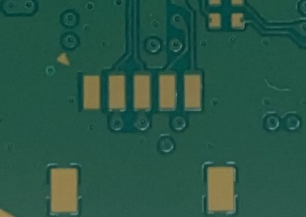
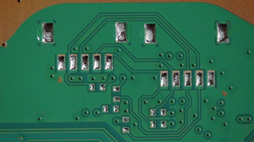
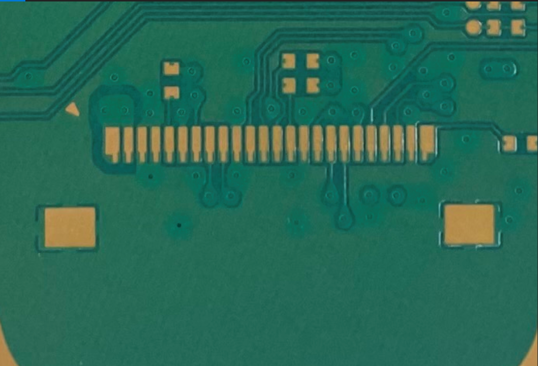
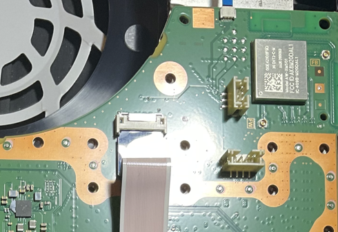
There are two Service Connectors on the PS5:
Pictures[edit | edit source]
First Connector (5 Pins)[edit | edit source]
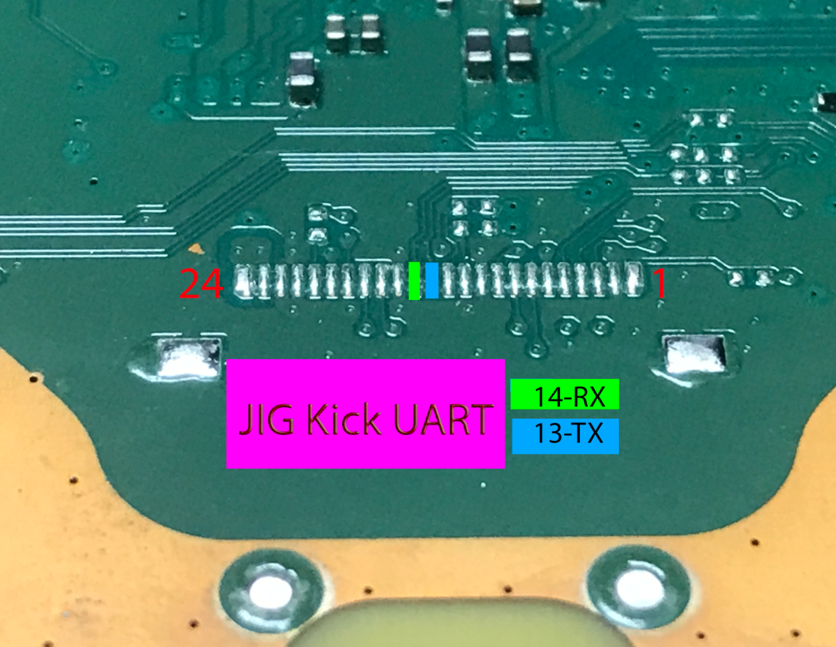
Second Connector (24 Pins)[edit | edit source]
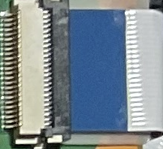
Third Connector (24 Pins) (Bluray)[edit | edit source]
Meaning of Pins[edit | edit source]
- Starts at Leftmost (Indicated by Arrow)
5 Pins[edit | edit source]
| PIN # (24 PIN#) | Meaning | Notes |
|---|---|---|
| 1 | Ground | Ground Plane |
| 2(7) | Transmit EMC | Used to send commands to EMC. command always <com>:<chk>\r\n |
| 3(6) | Receive EMC | Used to recv responses from EMC. response always <res>:<chk>\r\n |
| 4(14) | titania uart1 tx | titania uart1 tx (bootrom: 460800, eap fw, apu: 230400) |
| 5(13) | titania uart1 rx | titania uart1 rx (bootrom: 460800, eap fw, apu: 230400) |
24 Pins[edit | edit source]
- Major credits to shuffle2 for the complete pinout
| PIN # | Meaning | Notes |
|---|---|---|
| 1 | VDD | 5v |
| 2 | VDD | 5v |
| 3 | GND | Ground Plane |
| 4 | GND | Ground Plane |
| 5 | emc gpio a1 | pulling low at emc boot causes emc rom to enter uart shell @ 460800 |
| 6 | Receive EMC | Used to recv responses from EMC. response always <res>:<chk>\r\n (uart rx emc 115200) |
| 7 | Transmit EMC | Used to send commands to EMC. command always <com>:<chk>\r\n (uart tx emc 115200) |
| 8 | 3v3 | goes low when emc resets |
| 9 | 0v | 0v |
| 10 | GND | Ground Plane |
| 11 | titania uart0 tx | titania uart0 tx (efc fw: 460800) |
| 12 | titania uart0 rx | titania uart0 rx (efc fw: 460800) |
| 13 | titania uart1 rx | titania uart1 rx (bootrom: 460800, eap fw, apu: 230400) |
| 14 | titania uart1 tx | titania uart1 tx (bootrom: 460800, eap fw, apu: 230400) |
| 15 | GND | Ground Plane |
| 16 | emc gpio c5 | ("GPI SW" (only used if devif_det# active)) |
| 17 | 0v | 0v |
| 18 | 5v | 5v |
| 19 | emc gpio a49 | emc gpio a49 |
| 20 | emc gpio a27 | emc gpio a27. main power switch |
| 21 | i2c data | i2c data (i2c_bus_4) |
| 22 | i2c clock | (i2c_bus_4) |
| 23 | GND | Ground Plane |
| 24 | emc reset# | emc reset# |
