|
|
| (38 intermediate revisions by 3 users not shown) |
| Line 12: |
Line 12: |
|
| |
|
| ---- | | ---- |
| | See also http://blog.binaryninjas.org/?p=149 |
|
| |
|
| = Review: = | | = Review: = |
| Line 19: |
Line 20: |
| == Hardware == | | == Hardware == |
|
| |
|
| Teardown photo album: http://imgur.com/a/ytRW5 | | Teardown photo album: |
| | |
| | <gallery> |
| | File:08XyXC8.jpeg |
| | File:0xxrydw.jpeg |
| | File:1QbQhNT.jpeg |
| | File:2tP1Fkr.jpeg |
| | File:3pYanfF.jpeg |
| | File:3roUnDR.jpeg |
| | File:518jy4N.jpeg |
| | File:5Im3Fgp.jpeg |
| | File:65Ad9It.jpeg |
| | File:7863lo3.jpeg |
| | File:7j2y3oo.jpeg |
| | File:7KmRxHA.jpeg |
| | File:7P44HZO.jpeg |
| | File:7WKfCC3.jpeg |
| | File:8F49ttw.jpeg |
| | File:8FERmHB.jpeg |
| | File:9959nAv.jpeg |
| | File:A5iH1fU.jpeg |
| | File:AgSNuAc.jpeg |
| | File:AI7Rdbl.jpeg |
| | File:aTfnx2h.jpeg |
| | File:BSpanfM.jpeg |
| | File:bZ5cSTr.jpeg |
| | File:cQb6Hr1.jpeg |
| | File:cUnyoKl.jpeg |
| | File:cUYA7j0.jpeg |
| | File:dBsL3Kn.jpeg |
| | File:DJ72B6E.jpeg |
| | File:dlwiEcB.jpeg |
| | File:DsLZ3Xf.jpeg |
| | File:EK9DQlr.jpeg |
| | File:eWCknuC.jpeg |
| | File:FEZpxph.jpeg |
| | File:fpM5snu.jpeg |
| | File:Fu0xNxB.jpeg |
| | File:gF2Desn.jpeg |
| | File:GhxB4iO.jpeg |
| | File:GJAQ2eD.jpeg |
| | File:gRrEwoj.jpeg |
| | File:GT2AykA.jpeg |
| | File:h9Z3yTj.jpeg |
| | File:hJfdN6Y.jpeg |
| | File:HrtfxmV.jpeg |
| | File:i06VyHB.jpeg |
| | File:I0jeij5.jpeg |
| | File:I0joI3o.jpeg |
| | File:jeonlvc.jpeg |
| | File:jlWd7SD.jpeg |
| | File:JqFkPNl.jpeg |
| | File:KLiMprB.jpeg |
| | File:KlNxTRs.jpeg |
| | File:knOHMwu.jpeg |
| | File:Lz2nlfj.jpeg |
| | File:M4JZU4G.jpeg |
| | File:MhiDvQp.jpeg |
| | File:MnrEU9I.jpeg |
| | File:mqWy7Ba.jpeg |
| | File:obKO0F6.jpeg |
| | File:OfRdANo.jpeg |
| | File:oxeoZgI.jpeg |
| | File:pgYz4Xv.jpeg |
| | File:pNWE6LA.jpeg |
| | File:PQ8LAWP.jpeg |
| | File:PSvKqTz.jpeg |
| | File:pwxHJ40.jpeg |
| | File:q7gco24.jpeg |
| | File:qI4xNec.jpeg |
| | File:qyq5smd.jpeg |
| | File:qZZmJKF.jpeg |
| | File:rpzexY0.jpeg |
| | File:rURuqlE.jpeg |
| | File:rvMaQwI.jpeg |
| | File:s4jqagj.jpeg |
| | File:SihQjR8.jpeg |
| | File:TetUWkG.jpeg |
| | File:TFIhArd.jpeg |
| | File:TXHghgH.jpeg |
| | File:TYO2asR.jpeg |
| | File:U3rNHQz.jpeg |
| | File:UBLV6U4.jpeg |
| | File:Vyxc25e.jpeg |
| | File:Vyxr0fy.jpeg |
| | File:w3JMMiF.jpeg |
| | File:WeuZtOU.jpeg |
| | File:WK3b3Dr.jpeg |
| | File:WuRl1Ft.jpeg |
| | File:XChVTGI.jpeg |
| | File:XEmYZxP.jpeg |
| | File:Y2CjPuI.jpeg |
| | File:yeSWiWW.jpeg |
| | File:YgBOdWe.jpeg |
| | File:YJzxLnN.jpeg |
| | File:Z1H6a1K.jpeg |
| | File:zJw7iXa.jpeg |
| | File:ztfuGtq.jpeg |
| | </gallery> |
| | |
| | Source: http://imgur.com/a/ytRW5 |
|
| |
|
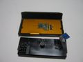
| The USB port and LED are on one separate board, connected using a [http://en.wikipedia.org/wiki/Flexible_flat_cable flat flexible cable], this cable is connected to a vertical FFC connector that does not have a locking mechanism. | | The USB port and LED are on one separate board, connected using a [http://en.wikipedia.org/wiki/Flexible_flat_cable flat flexible cable], this cable is connected to a vertical FFC connector that does not have a locking mechanism. |
|
| |
|
| The touchpad sensor is also detachable, connected using a flat flexible cable, this cable is connected to the main PCB using a connector that has a flip-up locking mechanism.
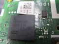
| | '''Main microcontroller:''' is a Spansion MB9BF002, a ARM Cortex M3 core, Ball Grid Array (BGA) package. The reset and SWD signals might be exposed to test points, I am not sure. |
| | |
| | '''Power Management IC (PMIC):''' There's a ROHM chip marked with "BD9200" (in QFN 32 pin footprint), it has some thick traces around it, plus a big inductor. One of the pins near it read 6V, might be for the motor. |
|
| |
|
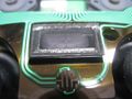
| The speaker is not removable and it connects to the main PCB using some raised contacts.
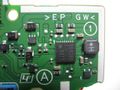
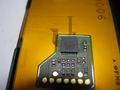
| | '''Bluetooth module:''' shows "8LA18366" and "GS-WCM-01" and "VR2.0". There is also a [http://en.wikipedia.org/wiki/QR_code QR code] that I can't decipher yet. There are a lot of test points near it. Underneath the EMI shields, it is confirmed to be a [http://www.qca.qualcomm.com/wp-content/uploads/2013/11/AR3002.pdf Qualcomm Atheros AR3002-BL3D]. |
|
| |
|
| The battery is 3.65V 1000mAH Li-ion.
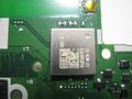
| | '''Six-axis sensor:''' There's a rectangular, maybe Land grid array (LGA) chip on the bottom side on the left, marked with "134" "A1322" "333": [http://www.bosch-sensortec.com/en/homepage/products_3/6_axis_sensors_2/inertial_measurement_unit_1/bmi055_1/bmi055 Bosch-sensortec GMBH BMI055] inertial sensor used for the three-axis gyroscope and three-axis accelerometer. It's got some sort of latch signal around it, or maybe it's a weird clock. It's slow and doesn't seem like a bus. Or it could be a shift register and it's reading blank because I'm not pressing buttons. |
|
| |
|
| Main microcontroller is a Spansion MB9BF002, a ARM Cortex M3 core, BGA package. The reset and SWD signals might be exposed to test points, I am not sure.
| | '''Touchpad sensor:''' (with Atmel 8-bit AVR Microcontroller ATiny2313) is also detachable, connected using a flat flexible cable, this cable is connected to the main PCB using a connector that has a flip-up locking mechanism. |
|
| |
|
| The Bluetooth module shows "8LA18366" and "GS-WCM-01" (or maybe it's "GS-WCN-01") and "VR2.0". There is also a QR code that I can't decipher yet. There are a lot of test points near it. Underneath, it is confirmed to be a Qualcomm Atheros AR3002.
| | '''Speaker:''' (EAS1S181F) is a built-in [http://en.wikipedia.org/wiki/Loudspeaker#Piezoelectric_speakers Piezoelectric speaker] connected to the main PCB using some raised contacts. |
|
| |
|
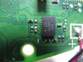
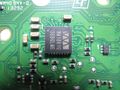
| There's a chip marked with "BD9200" (in QFN 32 pin footprint) that might be a PMIC because it has some thick traces around it, plus a big inductor. One of the pins near it read 6V, might be for the motor. | | '''Audio codecs:''' There's a {{G|QFN}} 32 pin chip marked with "WM1801G" (Wolfson Microelectronics) "36A0LM6" dead center on the bottom side of the PCB. It is near the audio stuff but it is also near where all the buttons connect. There are 5 test points near it. It appears to be communicating with {{G|SPI BUS}} with constant activity. There's also two resistors that look like {{G|I²C}} pull-up resistors, and there appears to be constant I2C traffic. |
|
| |
|
| There's a shiny small square chip left of the left analog stick, it is marked with "7710" "325A1", I have no idea what this is, but there's some differential signals coming out of it, it might be USB, the activity stops when I disconnect the USB cable. I think this is connected to the USB port. I suspect this is a OTG chip. | | There's a shiny small square chip left of the left analog stick, it is marked with "7710" "325A1", I have no idea what this is, but there's some differential signals coming out of it, it might be USB, the activity stops when I disconnect the USB cable. I think this is connected to the USB port. I suspect this is a OTG chip. |
|
| |
| There's a rectangular (maybe LGA) chip on the bottom side on the left, marked with "134" "A1322" "333", possibly a sensor. It's got some sort of latch signal around it, or maybe it's a weird clock. It's slow and doesn't seem like a bus. Or it could be a shift register and it's reading blank because I'm not pressing buttons.
| |
|
| |
| There's a QFN 32 pin chip marked with "WM18016" (the M could be a N, the 6 could be a G) "36A0LM6" dead center on the bottom side of the PCB. It has a sine wave logo on it (possibly Wolfson Microelectronics). It is near the audio stuff but it is also near where all the buttons connect. There are 5 test points near it. It appears to be communicating with SPI with constant activity. There's also two resistors that look like I2C pull-up resistors, and there appears to be constant I2C traffic.
| |
|
| |
|
| Some buttons are active low, some are active high (maybe only the thumbstick push buttons). The sheet of flexible circuit for the buttons are active low. | | Some buttons are active low, some are active high (maybe only the thumbstick push buttons). The sheet of flexible circuit for the buttons are active low. |
|
| |
|
| I'll keep adding to this section
| | <gallery mode="nolines" widths="120px" heights="120px"> |
| | File:ARM_Cortex-M3-MB9BF002.jpg|Main Micro-controller |
| | File:PMIC_BD9200.jpg|Power Management |
| | File:Atheros_AR3002.jpg|Bluetooth Module and on the left, the numbering for the flexible film. |
| | File:6-axis_bosch-bmi055.jpg|6-axis |
| | File:TouchPad-002-DS4.jpg|TouchPad |
| | File:TouchPad_AT2313.jpg|TouchPad |
| | File:Speaker-DS4-002.jpg|LoudSpeaker |
| | File:WM1801G.jpg|Audio Codecs |
| | </gallery> |
|
| |
|
| === Flexible Film Pin Mapping === | | === Flexible Film Pin Mapping === |
| Line 53: |
Line 161: |
| See main page (skewed button connector) for pins purpose. | | See main page (skewed button connector) for pins purpose. |
|
| |
|
| =USB= | | === Replacing Parts / Mod === |
| | | * http://www.neogaf.com/forum/showthread.php?t=867944 Dualshock 4 with Xbox One analog sticks |
| Audio definitely does not carry through USB.
| | * http://www.eurogamer.net/articles/digitalfoundry-2016-how-to-upgrade-your-dual-shock-4-with-xbox-one-parts |
| | | * https://www.reddit.com/r/PS4/comments/2rtimv/diy_double_dualshock_4_battery_capacity_internal/ |
| The reports arrive once every 4ms.
| |
| | |
| ===Device Descriptor===
| |
| | |
| {| class="wikitable"
| |
| |-
| |
| ! colspan="5" style="background-color:#C0C0C0; color:#000000;" |[http://linuxcommand.org/man_pages/lsusb8.html Device Descriptor]
| |
| |-
| |
| ! Offset
| |
| ! Field
| |
| ! Size
| |
| ! Value
| |
| ! Description
| |
| |-
| |
| | 0 || bLength || 1 || 0x12 || Size of this descriptor in bytes (18)
| |
| |-
| |
| | 1 || bDescriptorType || 1 || 0x01 || DEVICE descriptor type (Constant = 1)
| |
| |-
| |
| | 2 || bcdUSB || 2 || 0x0200 || USB Spec release number ([http://en.wikipedia.org/wiki/USB#USB_2.0 2.00]):
| |
| <small>with which the device and is descriptors are compliant (e.g.: 0x0200 (USB2.0), 0x0300,
| |
| ([[USB_3.0|USB3.0]]))</small>
| |
| |-
| |
| | 4 || bDeviceClass || 1 || 0x00 || [http://www.usb.org/developers/defined_class Class code] assigned by [http://en.wikipedia.org/wiki/USB_Implementers_Forum USB-IF:]
| |
| <small>(used by the operating system to find a class driver for your device)</small>
| |
| <small>
| |
| *00h means each interface defines its own class (identify itself at the interface level: bInterfaceClass)
| |
| *FFh means vendor-defined class
| |
| *Any other value must be a class code
| |
| </small>
| |
| |-
| |
| | 5 || bDeviceSubClass || 1 || 0x00 || SubClass Code assigned by USB-IF
| |
| <small>(used by the operating system to find a class driver for your device)</small>
| |
| |-
| |
| | 6 || bDeviceProtocol || 1 || 0x00 || Protocol Code assigned by USB-IF
| |
| <small>(used by the operating system to find a class driver for your device)</small>
| |
| |-
| |
| | 7 || bMaxPacketSize0 || 1 || 0x40 || Max packet size for endpoint 0. (64)
| |
| <small>
| |
| *Must be 8, 16, 32 or 64
| |
| *Must be 9 according to [http://www.usb.org/developers/tools/USB30CVSpec_1_4.pdf Compliance Test Specification for the USB 3.0 Architecture p29 9.1]
| |
| </small>
| |
| |-
| |
| | 8 || idVendor || 2 || 0x054C || [http://www.linux-usb.org/usb.ids Vendor ID (VID)] (Sony Corp.)
| |
| <small>
| |
| must be obtained from USB-IF
| |
| | |
| (used by the operating system to find a driver for your device)</small>
| |
| |-
| |
| | 10 || idProduct || 2 || 0x05C4 || Product ID (PID) - (Sony Computer Entertainment Wireless Controller)
| |
| <small>
| |
| assigned by the manufacturer
| |
| | |
| (used by the operating system to find a driver for your device)</small>
| |
| |-
| |
| | 12 || bcdDevice || 2 || 0x0100 || Device release number (Version: 1.00)
| |
| <small>in binary coded decimal</small>
| |
| |-
| |
| | 14 || iManufacturer || 1 || 0x01 || Index of string descriptor describing manufacturer
| |
| <small>set to 0 if no string</small>
| |
| |-
| |
| | 15 || iProduct || 1 || 0x02 || Index of string descriptor describing product
| |
| <small>set to 0 if no string</small>
| |
| |-
| |
| | 16 || iSerialNumber || 1 || 0x00 || Index of string descriptor describing device serial number<BR /> <small>set to 0 if no string</small>
| |
| |-
| |
| | 17 || bNumConfigurations || 1 || 0x01 || Number of possible configurations
| |
| |-
| |
| |}
| |
| | |
| ===Configuration Descriptor===
| |
| | |
| {| class="wikitable"
| |
| |-
| |
| ! colspan="5" style="background-color:#C0C0C0; color:#000000;" |Configuration Descriptor
| |
| |-
| |
| ! Offset
| |
| ! Field
| |
| ! Size
| |
| ! Value
| |
| ! Description
| |
| |-
| |
| | 0 || bLength || 1 || 0x09 || Size
| |
| |-
| |
| | 1 || bDescriptorType || 1 || 0x02 || (= 2)
| |
| |-
| |
| | 2 || wTotalLength || 2 || 0x0029 || Total number of bytes (41) in this descriptor and all the following descriptors (9+9+9+7+7)
| |
| |-
| |
| | 4 || bNumInterfaces || 1 || 0x01 || Number of interfaces supported by this configuration
| |
| |-
| |
| | 5 || bConfigurationValue || 1 || 0x01 || Value used by Set Configuration to select this configuration
| |
| |-
| |
| | 6 || iConfiguration || 1 || 0x00 || Index of string descriptor describing configuration - set to 0 if no string
| |
| |-
| |
| | 7 || bmAttributes || 1 || 0xC0 || Self Powered & powered by the bus (11000000) (PS3 controller: 0x80)
| |
| <small>
| |
| specify power parameters for the configuration :
| |
| <small>
| |
| {| cellpadding="4" style="border-collapse: collapse; text-align: center;"
| |
| |-
| |
| | colspan="6" |<code><sub>msb</sub>''<sup>8-Digit bit binary</sup>''<sub>lsb</sub></code>
| |
| |-
| |
| |style="border: 1px solid; border-left: hidden;" | …
| |
| |style="border: 1px solid;" | 7|6|5|4|3|2|1|0
| |
| |style="border: 1px solid; border-right: hidden;" | …
| |
| |}
| |
| </small>
| |
| *D0 - D4: Reserved. | |
| *D5: The configuration supports remote wakeup.
| |
| *D6: The configuration is self-powered and does not use power from the bus.
| |
| *D7: The configuration is powered by the bus.
| |
| </small>
| |
| |-
| |
| | 8 || bMaxPower || 1 || 0xFA || Maximum current: 500mA drawn by device in this configuration.<BR /><small>In units of 2mA. So 0x32 (50) means 100 mA</small>
| |
| |-
| |
| ! colspan="5" style="background-color:#C0C0C0; color:#000000;" |Interface Descriptor
| |
| |-
| |
| | 0 || bLength || 1 || 0x09 || Size
| |
| |-
| |
| | 1 || bDescriptorType || 1 || 0x04 || (= 4)
| |
| |-
| |
| | 2 || bInterfaceNumber || 1 || 0x00 || Number identifying this interface.
| |
| <small>Zero-based value</small>
| |
| |-
| |
| | 3 || bAlternateSetting || 1 || 0x00 || The first (and default) value used to select alternative setting is always 0
| |
| <small>
| |
| (An interface can have more than one variant, and these variants can be switched between, while other interfaces are still in operation)
| |
| </small>
| |
| |-
| |
| | 4 || bNumEndpoints || 1 || 0x02 || Number of Endpoints used for this interface
| |
| |-
| |
| | 5 || bInterfaceClass || 1 || 0x03 || Class code assigned by USB-IF]
| |
| <small>
| |
| *00h is a reserved value
| |
| *FFh means vendor-defined class
| |
| *Any other value must be a class code
| |
| </small>
| |
| |-
| |
| | 6 || bInterfaceSubClass || 1 || 0x00 || SubClass Code assigned by USB-IF
| |
| |-
| |
| | 7 || bInterfaceProtocol || 1 || 0x00 || Protocol Code assigned by USB-IF
| |
| |-
| |
| | 8 || iInterface || 1 || 0x00 || Index of string descriptor describing interface - set to 0 if no string
| |
| |-
| |
| ! colspan="5" style="background-color:#C0C0C0; color:#000000;" |Human Interface Device (HID) Descriptor
| |
| |-
| |
| | 0 || bLength || 1 || 0x09 || Size
| |
| |-
| |
| | 1 || bDescriptorType || 1 || 0x21 || Constant name specifying type of HID descriptor
| |
| |-
| |
| | 2 || bcdHID 1.17 || 2 || 0x0111 || [http://en.wikipedia.org/wiki/USB_human_interface_device_class HID class spec version] (1.11)
| |
| |-
| |
| | 4 || bCountryCode || 1 || 0x00 || Not supported ([http://www.usb.org/developers/devclass_docs/HID1_11.pdf Device Class Definition for HID 1.11 6.2.1 p33])
| |
| |-
| |
| | 5 || bNumDescriptors || 1 || 0x01 || Number of Descriptors
| |
| |-
| |
| | 6 || bDescriptorType || 1 || 0x22 || DescriptorType (34): REPORT
| |
| |-
| |
| | 7 || DescriptorLength || 2 || 0x01D3 || total size of the Report descriptor (467)
| |
| |-
| |
| ! colspan="5" style="background-color:#C0C0C0; color:#000000;" |Endpoint (IN) Descriptor
| |
| |-
| |
| | 0 || bLength || 1 || 0x07 || Size
| |
| |-
| |
| | 1 || bDescriptorType || 1 || 0x05 || (= 5)
| |
| |-
| |
| | 2 || bEndpointAddress || 1 || 0x84 || IN/D2H (10000100)-->4 (PS3 Controller: 0x81)
| |
| <small>
| |
| The address of this endpoint within the device:
| |
| *D3-D0: Endpoint number
| |
| *D6-D4: Reserved. set to Zero
| |
| *D7: Direction: 0 = OUT, 1 = IN (Ignored for Control Endpoints)
| |
| </small>
| |
| |-
| |
| | 3 || bmAttributes || 1 || 0x03 || Interrupt (00000011)
| |
| <small>
| |
| (D1:0) [http://www.inno-logic.com/resources/21.php#4 Transfer Type:]
| |
| *00 = Control
| |
| *01 = Isochronous
| |
| *10 = Bulk
| |
| *11 = Interrupt
| |
| | |
| The following only apply to isochronous endpoints. Else set to 0.
| |
| | |
| (D3:2) Synchronisation Type (ISO mode):
| |
| *00 = No Synchronisation
| |
| *01 = Asynchronous
| |
| *10 = Adaptive
| |
| *11 = Synchronous
| |
| | |
| (D5:4) Usage Type (ISO mode):
| |
| *00 = Data endpoint | |
| *01 = Feedback endpoint
| |
| *10 = Implicit feedback Data endpoint
| |
| *11 = Reserved
| |
| | |
| (D7:6) Reserved
| |
| Set to 0
| |
| </small>
| |
| |-
| |
| | 4 || wMaxPacketSize || 2 || 0x0040 || (64)
| |
| |-
| |
| | 6 || bInterval || 1|| 0x05 || 5 (unit depends on device speed) (PS3 Controller: 1)
| |
| <small>
| |
| Interval for polling endpoint for data transfers. Expressed in frames (ms) for low/full speed or microframes (125{{micro}}s) for high speed<BR />
| |
| (ignored for Bulk & Control Endpoints. Isochronous must equal 1 and field may range from 1 to 255 for interrupt endpoints)
| |
| </small>
| |
| |-
| |
| ! colspan="5" style="background-color:#C0C0C0; color:#000000;" |Endpoint (OUT) Descriptor
| |
| |-
| |
| | 0 || bLength || 1 || 0x07 || Size
| |
| |-
| |
| | 1 || bDescriptorType || 1 || 0x05 || (= 5)
| |
| |-
| |
| | 2 || bEndpointAddress || 1 || 0x03 || OUT/H2D (00000011)-->3 (PS3 Controller: 0x02)
| |
| |-
| |
| | 3 || bmAttributes || 1 || 0x03 || Interrupt
| |
| |-
| |
| | 4 || wMaxPacketSize || 2 || 0x0040 || (64)
| |
| |-
| |
| | 6 || bInterval || 1 || 0x05 || 5
| |
| |-
| |
| |}
| |
| | |
| === HID Report Descriptor ===
| |
| | |
| [http://www.usb.org/developers/devclass_docs/Hut1_12v2.pdf HID Usage Tables 1.12 (p.26)]
| |
| | |
| <div style="height:650px; width:700px; overflow:auto">
| |
| | |
| {| class="wikitable sortable"
| |
| |-
| |
| ! colspan="3"|Value !! Items !! Remarks
| |
| |-
| |
| |0x05||0x01|| - ||Usage Page (Generic Desktop Controls)||
| |
| |-
| |
| |0x09||0x05|| - ||Usage (Game Pad)|| CA – <small>A manual control or cursor device. A game pad minimally consists of a thumb-activated rocker switch that controls two axes (X and Y) and has four buttons. The rocker switch consists of four contact closures for up, down, right, and left.</small>
| |
| |-
| |
| |0xA1||0x01|| - ||Collection (Application)|| Start
| |
| |-
| |
| |0x85||0x01|| - ||Report ID (1)|| <small>Used by the FW to determine what data has been send or need to be transmitted</small>
| |
| |-
| |
| |0x09||0x30|| - ||Usage (X)|| DV – <small>A linear translation in the X direction. Report values should increase as the control’s position is moved from left to right. (for sticks)</small>
| |
| |-
| |
| |0x09||0x31|| - ||Usage (Y)|| DV – <small>(Y direction- values should increase from far to near)</small>
| |
| |-
| |
| |0x09||0x32|| - ||Usage (Z)|| DV – <small>(Z direction- values should increase from high to low)</small>
| |
| |-
| |
| |0x09||0x35|| - ||Usage (Rz)|| DV – <small>A rotation about the Z axis. Angular position report values follow the righthand rule.</small>
| |
| |-
| |
| |0x15||0x00|| - ||Logical Minimum (0)|| Value for sticks
| |
| |-
| |
| |0x26||0xFF|| 0x00 ||Logical Maximum (255)|| Value
| |
| |-
| |
| |0x75||0x08|| - ||Report Size (8)|| 8 bits per variable
| |
| |-
| |
| |0x95||0x04|| - ||Report Count (4)|| 4 variables
| |
| |-
| |
| |0x81||0x02|| - ||Input (Data,Var,Abs,No Wrap,Linear,Preferred State,No Null Position)|| send variables (bytes 01 to 04)
| |
| |-
| |
| |0x09||0x39|| - ||Usage (Hat switch)|| DV – <small>A specialized mechanical configuration of switches generating a variable value with a null state. The switches are arranged around a springloaded knob. When the knob is tilted in the direction of a switch, its contacts are closed. A typical example is four switches that are capable of generating information about four possible directions in which the knob can be tilted. Intermediate positions can also be decoded if the hardware allows two switches to be reported simultaneously. (for D-pad)</small>
| |
| |-
| |
| |0x15||0x00|| - ||Logical Minimum (0)|| Value (0=N)
| |
| |-
| |
| |0x25||0x07|| - ||Logical Maximum (7)|| Value (7=NW)
| |
| |-
| |
| |0x35||0x00|| - ||Physical Minimum (0)||
| |
| |-
| |
| |0x46||0x3B||0x01||Physical Maximum (315)||
| |
| |-
| |
| |0x65||0x14|| - ||Unit (System: English Rotation, Length: Centimeter)||
| |
| |-
| |
| |0x75||0x04|| - ||Report Size (4)|| (4 bits)
| |
| |-
| |
| |0x95||0x01|| - ||Report Count (1)|| 1 variable (D-pad)
| |
| |-
| |
| |0x81||0x42|| - ||Input (Data,Var,Abs,No Wrap,Linear,Preferred State,Null State)|| send (byte 05 low nibble -lsb)
| |
| |-
| |
| |0x65||0x00|| - ||Unit (None)||
| |
| |-
| |
| |0x05||0x09|| - ||Usage Page (Button) || face buttons
| |
| |-
| |
| |0x19||0x01|| - ||Usage Minimum (0x01)|| first button
| |
| |-
| |
| |0x29||0x0E|| - ||Usage Maximum (0x0E)|| last button (14)
| |
| |-
| |
| |0x15||0x00|| - ||Logical Minimum (0)|| Value for each button (status: 0 or 1)
| |
| |-
| |
| |0x25||0x01|| - ||Logical Maximum (1)||
| |
| |-
| |
| |0x75||0x01|| - ||Report Size (1)|| 1 bit per button
| |
| |-
| |
| |0x95||0x0E|| - ||Report Count (14)|| 14 bits
| |
| |-
| |
| |0x81||0x02|| - ||Input (Data,Var,Abs,No Wrap,Linear,Preferred State,No Null Position)|| send (byte 05 high nibble msb, 8 bits of byte 06 and binary bit 0 & 1 of byte 07)
| |
| |-
| |
| |0x06||0x00||0xFF||Usage Page (Vendor Defined 0xFF00)||
| |
| |-
| |
| |0x09||0x20|| - ||Usage (0x20)|| Counter
| |
| |-
| |
| |0x75||0x06|| - ||Report Size (6)|| 6 bits
| |
| |-
| |
| |0x95||0x01|| - ||Report Count (1)||
| |
| |-
| |
| |0x15||0x00|| - ||Logical Minimum (0)||
| |
| |-
| |
| |0x25||0x7F|| - ||Logical Maximum (127)||
| |
| |-
| |
| |0x81||0x02|| - ||Input (Data,Var,Abs,No Wrap,Linear,Preferred State,No Null Position)|| send (byte 07: msb 6 bits)
| |
| |-
| |
| |0x05||0x01|| - ||Usage Page (Generic Desktop Controls)|| Shoulderpads Trigger
| |
| |-
| |
| |0x09||0x33|| - ||Usage (Rx)|| DV – <small>A rotation about the X axis. Angular position report values follow the right hand rule (L2 trigger)</small>
| |
| |-
| |
| |0x09||0x34|| - ||Usage (Ry)|| DV – <small>A rotation about the Z axis. Angular position report values follow the right hand rule (R2 trigger)</small>
| |
| |-
| |
| |0x15||0x00|| - ||Logical Minimum (0)||
| |
| |-
| |
| |0x26||0xFF||0x00||Logical Maximum (255)||
| |
| |-
| |
| |0x75||0x08|| - ||Report Size (8)|| 8 bits
| |
| |-
| |
| |0x95||0x02|| - ||Report Count (2)|| 2 bytes
| |
| |-
| |
| |0x81||0x02|| - ||Input (Data,Var,Abs,No Wrap,Linear,Preferred State,No Null Position)|| send bytes 08 & 09
| |
| |-
| |
| |0x06||0x00||0xFF||Usage Page (Vendor Defined 0xFF00)||
| |
| |-
| |
| |0x09||0x21|| - ||Usage (0x21)||
| |
| |-
| |
| |0x95||0x36|| - ||Report Count (54)||
| |
| |-
| |
| |0x81||0x02|| - ||Input (Data,Var,Abs,No Wrap,Linear,Preferred State,No Null Position)||
| |
| |-
| |
| |0x85||0x05|| - ||Report ID (5)||
| |
| |-
| |
| |0x09||0x22|| - ||Usage (0x22)||
| |
| |-
| |
| |0x95||0x1F|| - ||Report Count (31)||
| |
| |-
| |
| |0x91||0x02|| - ||Output (Data,Var,Abs,No Wrap,Linear,Preferred State,No Null Position,Non-volatile)||
| |
| |-
| |
| |0x85||0x04|| - ||Report ID (4)||
| |
| |-
| |
| |0x09||0x23|| - ||Usage (0x23)||
| |
| |-
| |
| |0x95||0x24|| - ||Report Count (36)||
| |
| |-
| |
| |0xB1||0x02|| - ||Feature (Data,Var,Abs,No Wrap,Linear,Preferred State,No Null Position,Non-volatile)|| DV – <small>declared in an Input report and is used as a notification to the host that the contents of a specific Feature report has changed</small>
| |
| |-
| |
| |0x85||0x02|| - ||Report ID (2)||
| |
| |-
| |
| |0x09||0x24|| - ||Usage (0x24)||
| |
| |-
| |
| |0x95||0x24|| - ||Report Count (36)||
| |
| |-
| |
| |0xB1||0x02|| - ||Feature (Data,Var,Abs,No Wrap,Linear,Preferred State,No Null Position,Non-volatile)||
| |
| |-
| |
| |0x85||0x08|| - ||Report ID (8)||
| |
| |-
| |
| |0x09||0x25|| - ||Usage (0x25)||
| |
| |-
| |
| |0x95||0x03|| - ||Report Count (3)||
| |
| |-
| |
| |0xB1||0x02|| - ||Feature (Data,Var,Abs,No Wrap,Linear,Preferred State,No Null Position,Non-volatile)||
| |
| |-
| |
| |0x85||0x10|| - ||Report ID (16)||
| |
| |-
| |
| |0x09||0x26|| - ||Usage (0x26)||
| |
| |-
| |
| |0x95||0x04|| - ||Report Count (4)||
| |
| |-
| |
| |0xB1||0x02|| - ||Feature (Data,Var,Abs,No Wrap,Linear,Preferred State,No Null Position,Non-volatile)||
| |
| |-
| |
| |0x85||0x11|| - ||Report ID (17)||
| |
| |-
| |
| |0x09||0x27|| - ||Usage (0x27)||
| |
| |-
| |
| |0x95||0x02|| - ||Report Count (2)||
| |
| |-
| |
| |0xB1||0x02|| - ||Feature (Data,Var,Abs,No Wrap,Linear,Preferred State,No Null Position,Non-volatile)||
| |
| |-
| |
| |0x85||0x12|| - ||Report ID (18)||
| |
| |-
| |
| |0x06||0x02||0xFF||Usage Page (Vendor Defined 0xFF02)||
| |
| |-
| |
| |0x09||0x21|| - ||Usage (0x21)||
| |
| |-
| |
| |0x95||0x0F|| - ||Report Count (15)||
| |
| |-
| |
| |0xB1||0x02|| - ||Feature (Data,Var,Abs,No Wrap,Linear,Preferred State,No Null Position,Non-volatile)||
| |
| |-
| |
| |0x85||0x13|| - ||Report ID (19)||
| |
| |-
| |
| |0x09||0x22|| - ||Usage (0x22)||
| |
| |-
| |
| |0x95||0x16|| - ||Report Count (22)||
| |
| |-
| |
| |0xB1||0x02|| - ||Feature (Data,Var,Abs,No Wrap,Linear,Preferred State,No Null Position,Non-volatile)||
| |
| |-
| |
| |0x85||0x14|| - ||Report ID (20)||
| |
| |-
| |
| |0x06||0x05||0xFF||Usage Page (Vendor Defined 0xFF05)||
| |
| |-
| |
| |0x09||0x20|| - ||Usage (0x20)||
| |
| |-
| |
| |0x95||0x10|| - ||Report Count (16)||
| |
| |-
| |
| |0xB1||0x02|| - ||Feature (Data,Var,Abs,No Wrap,Linear,Preferred State,No Null Position,Non-volatile)||
| |
| |-
| |
| |0x85||0x15|| - ||Report ID (21)||
| |
| |-
| |
| |0x09||0x21|| - ||Usage (0x21)||
| |
| |-
| |
| |0x95||0x2C|| - ||Report Count (44)||
| |
| |-
| |
| |0xB1||0x02|| - ||Feature (Data,Var,Abs,No Wrap,Linear,Preferred State,No Null Position,Non-volatile)||
| |
| |-
| |
| |0x06||0x80||0xFF||Usage Page (Vendor Defined 0xFF80)||
| |
| |-
| |
| |0x85||0x80|| - ||Report ID (128)||
| |
| |-
| |
| |0x09||0x20|| - ||Usage (0x20)||
| |
| |-
| |
| |0x95||0x06|| - ||Report Count (6)||
| |
| |-
| |
| |0xB1||0x02|| - ||Feature (Data,Var,Abs,No Wrap,Linear,Preferred State,No Null Position,Non-volatile)||
| |
| |-
| |
| |0x85||0x81|| - ||Report ID (129)||
| |
| |-
| |
| |0x09||0x21|| - ||Usage (0x21)||
| |
| |-
| |
| |0x95||0x06|| - ||Report Count (6)||
| |
| |-
| |
| |0xB1||0x02|| - ||Feature (Data,Var,Abs,No Wrap,Linear,Preferred State,No Null Position,Non-volatile)||
| |
| |-
| |
| |0x85||0x82|| - ||Report ID (130)||
| |
| |-
| |
| |0x09||0x22|| - ||Usage (0x22)||
| |
| |-
| |
| |0x95||0x05|| - ||Report Count (5)||
| |
| |-
| |
| |0xB1||0x02|| - ||Feature (Data,Var,Abs,No Wrap,Linear,Preferred State,No Null Position,Non-volatile)||
| |
| |-
| |
| |0x85||0x83|| - ||Report ID (131)||
| |
| |-
| |
| |0x09||0x23|| - ||Usage (0x23)||
| |
| |-
| |
| |0x95||0x01|| - ||Report Count (1)||
| |
| |-
| |
| |0xB1||0x02|| - ||Feature (Data,Var,Abs,No Wrap,Linear,Preferred State,No Null Position,Non-volatile)||
| |
| |-
| |
| |0x85||0x84|| - ||Report ID (132)||
| |
| |-
| |
| |0x09||0x24|| - ||Usage (0x24)||
| |
| |-
| |
| |0x95||0x04|| - ||Report Count (4)||
| |
| |-
| |
| |0xB1||0x02|| - ||Feature (Data,Var,Abs,No Wrap,Linear,Preferred State,No Null Position,Non-volatile)||
| |
| |-
| |
| |0x85||0x85|| - ||Report ID (133)||
| |
| |-
| |
| |0x09||0x25|| - ||Usage (0x25)||
| |
| |-
| |
| |0x95||0x06|| - ||Report Count (6)||
| |
| |-
| |
| |0xB1||0x02|| - ||Feature (Data,Var,Abs,No Wrap,Linear,Preferred State,No Null Position,Non-volatile)||
| |
| |-
| |
| |0x85||0x86|| - ||Report ID (134)||
| |
| |-
| |
| |0x09||0x26|| - ||Usage (0x26)||
| |
| |-
| |
| |0x95||0x06|| - ||Report Count (6)||
| |
| |-
| |
| |0xB1||0x02|| - ||Feature (Data,Var,Abs,No Wrap,Linear,Preferred State,No Null Position,Non-volatile)||
| |
| |-
| |
| |0x85||0x87|| - ||Report ID (135)||
| |
| |-
| |
| |0x09||0x27|| - ||Usage (0x27)||
| |
| |-
| |
| |0x95||0x23|| - ||Report Count (35)||
| |
| |-
| |
| |0xB1||0x02|| - ||Feature (Data,Var,Abs,No Wrap,Linear,Preferred State,No Null Position,Non-volatile)||
| |
| |-
| |
| |0x85||0x88|| - ||Report ID (136)||
| |
| |-
| |
| |0x09||0x28|| - ||Usage (0x28)||
| |
| |-
| |
| |0x95||0x22|| - ||Report Count (34)||
| |
| |-
| |
| |0xB1||0x02|| - ||Feature (Data,Var,Abs,No Wrap,Linear,Preferred State,No Null Position,Non-volatile)||
| |
| |-
| |
| |0x85||0x89|| - ||Report ID (137)||
| |
| |-
| |
| |0x09||0x29|| - ||Usage (0x29)||
| |
| |-
| |
| |0x95||0x02|| - ||Report Count (2)||
| |
| |-
| |
| |0xB1||0x02|| - ||Feature (Data,Var,Abs,No Wrap,Linear,Preferred State,No Null Position,Non-volatile)||
| |
| |-
| |
| |0x85||0x90|| - ||Report ID (144)||
| |
| |-
| |
| |0x09||0x30|| - ||Usage (X)|| DV – <small>A linear translation in the X direction. Report values should increase as the control’s position is moved from left to right.</small>
| |
| |-
| |
| |0x95||0x05|| - ||Report Count (5)||
| |
| |-
| |
| |0xB1||0x02|| - ||Feature (Data,Var,Abs,No Wrap,Linear,Preferred State,No Null Position,Non-volatile)||
| |
| |-
| |
| |0x85||0x91|| - ||Report ID (145)||
| |
| |-
| |
| |0x09||0x31|| - ||Usage (Y)|| DV – <small>A linear translation in the Y direction. Report values should increase as the control’s position is moved from far to near.</small>
| |
| |-
| |
| |0x95||0x03|| - ||Report Count (3)||
| |
| |-
| |
| |0xB1||0x02|| - ||Feature (Data,Var,Abs,No Wrap,Linear,Preferred State,No Null Position,Non-volatile)||
| |
| |-
| |
| |0x85||0x92|| - ||Report ID (146)||
| |
| |-
| |
| |0x09||0x32|| - ||Usage (Z)|| DV – <small>A linear translation in the Z direction. Report values should increase as the control’s position is moved from high to low (Z).</small>
| |
| |-
| |
| |0x95||0x03|| - ||Report Count (3)||
| |
| |-
| |
| |0xB1||0x02|| - ||Feature (Data,Var,Abs,No Wrap,Linear,Preferred State,No Null Position,Non-volatile)||
| |
| |-
| |
| |0x85||0x93|| - ||Report ID (147)||
| |
| |-
| |
| |0x09||0x33|| - ||Usage (Rx)|| DV – <small>A rotation about the X axis. Angular position report values follow the righthand rule.</small>
| |
| |-
| |
| |0x95||0x0C|| - ||Report Count (12)||
| |
| |-
| |
| |0xB1||0x02|| - ||Feature (Data,Var,Abs,No Wrap,Linear,Preferred State,No Null Position,Non-volatile)||
| |
| |-
| |
| |0x85||0xA0|| - ||Report ID (160)||
| |
| |-
| |
| |0x09||0x40|| - ||Usage (Vx)|| DV – <small>A vector in the X direction. Report values should increase as the vector increases in the positive X direction (from left to right). Negative values represent vectors in the negative X direction.</small>
| |
| |-
| |
| |0x95||0x06|| - ||Report Count (6)||
| |
| |-
| |
| |0xB1||0x02|| - ||Feature (Data,Var,Abs,No Wrap,Linear,Preferred State,No Null Position,Non-volatile)||
| |
| |-
| |
| |0x85||0xA1|| - ||Report ID (161)||
| |
| |-
| |
| |0x09||0x41|| - ||Usage (Vy)|| DV – <small>A vector in the Y direction. Report values should increase as the vector increases in the positive Y direction (from far to near). Negative values represent vectors in the negative Y direction.</small>
| |
| |-
| |
| |0x95||0x01|| - ||Report Count (1)||
| |
| |-
| |
| |0xB1||0x02|| - ||Feature (Data,Var,Abs,No Wrap,Linear,Preferred State,No Null Position,Non-volatile)||
| |
| |-
| |
| |0x85||0xA2|| - ||Report ID (162)||
| |
| |-
| |
| |0x09||0x42|| - ||Usage (Vz)|| DV – <small>(Z direction -from high to low)</small>
| |
| |-
| |
| |0x95||0x01|| - ||Report Count (1)||
| |
| |-
| |
| |0xB1||0x02|| - ||Feature (Data,Var,Abs,No Wrap,Linear,Preferred State,No Null Position,Non-volatile)||
| |
| |-
| |
| |0x85||0xA3|| - ||Report ID (163)||
| |
| |-
| |
| |0x09||0x43|| - ||Usage (Vbrx)|| DV – <small>A vector in the X direction relative to the body of an object. Report values should increase as the vector increases in the positive X direction (forward). Negative values represent vectors in the negative X direction. X is the “forward” axis for an object</small>
| |
| |-
| |
| |0x95||0x30|| - ||Report Count (48)||
| |
| |-
| |
| |0xB1||0x02|| - ||Feature (Data,Var,Abs,No Wrap,Linear,Preferred State,No Null Position,Non-volatile)||
| |
| |-
| |
| |0x85||0xA4|| - ||Report ID (164)||
| |
| |-
| |
| |0x09||0x44|| - ||Usage (Vbry)|| DV – <small>(Y direction -to the right from an observer facing forward on the object)</small>
| |
| |-
| |
| |0x95||0x0D|| - ||Report Count (13)||
| |
| |-
| |
| |0xB1||0x02|| - ||Feature (Data,Var,Abs,No Wrap,Linear,Preferred State,No Null Position,Non-volatile)||
| |
| |-
| |
| |0x85||0xA5|| - ||Report ID (165)||
| |
| |-
| |
| |0x09||0x45|| - ||Usage (Vbrz)|| DV – <small>A vector in the Z direction relative to the body of an object. Report values should increase as the vector increases in the positive Z direction (down from an observer facing forward on the object). Negative values represent vectors in the negative Z direction.</small>
| |
| |-
| |
| |0x95||0x15|| - ||Report Count (21)||
| |
| |-
| |
| |0xB1||0x02|| - ||Feature (Data,Var,Abs,No Wrap,Linear,Preferred State,No Null Position,Non-volatile)||
| |
| |-
| |
| |0x85||0xA6|| - ||Report ID (166)||
| |
| |-
| |
| |0x09||0x46|| - ||Usage (Vno)|| DV– <small>A non oriented vector or value. The units define a physical measurement not related to a specific axis or orientation. An example would be pressure or temperature.</small>
| |
| |-
| |
| |0x95||0x15|| - ||Report Count (21)||
| |
| |-
| |
| |0xB1||0x02|| - ||Feature (Data,Var,Abs,No Wrap,Linear,Preferred State,No Null Position,Non-volatile)||
| |
| |-
| |
| |0x85||0xF0|| - ||Report ID (240)||
| |
| |-
| |
| |0x09||0x47|| - ||Usage (Feature Notification)||
| |
| |-
| |
| |0x95||0x3F|| - ||Report Count (63)||
| |
| |-
| |
| |0xB1||0x02|| - ||Feature (Data,Var,Abs,No Wrap,Linear,Preferred State,No Null Position,Non-volatile)||
| |
| |-
| |
| |0x85||0xF1|| - ||Report ID (241)||
| |
| |-
| |
| |0x09||0x48|| - ||Usage (Resolution Multiplier)|| DV– <small>Defines a (if a device has the capability to vary the resolution of one or more of its controls) Resolution Multiplier for a (all) Control:</small>
| |
| |-
| |
| |0x95||0x3F|| - ||Report Count (63)||
| |
| |-
| |
| |0xB1||0x02|| - ||Feature (Data,Var,Abs,No Wrap,Linear,Preferred State,No Null Position,Non-volatile)||
| |
| |-
| |
| |0x85||0xF2|| - ||Report ID (242)||
| |
| |-
| |
| |0x09||0x49|| - ||Usage (0x49)||
| |
| |-
| |
| |0x95||0x0F|| - ||Report Count (15)||
| |
| |-
| |
| |0xB1||0x02|| - ||Feature (Data,Var,Abs,No Wrap,Linear,Preferred State,No Null Position,Non-volatile)||
| |
| |-
| |
| |0x85||0xA7|| - ||Report ID (167)||
| |
| |-
| |
| |0x09||0x4A|| - ||Usage (0x4A)||
| |
| |-
| |
| |0x95||0x01|| - ||Report Count (1)||
| |
| |-
| |
| |0xB1||0x02|| - ||Feature (Data,Var,Abs,No Wrap,Linear,Preferred State,No Null Position,Non-volatile)||
| |
| |-
| |
| |0x85||0xA8|| - ||Report ID (168)||
| |
| |-
| |
| |0x09||0x4B|| - ||Usage (0x4B)||
| |
| |-
| |
| |0x95||0x01|| - ||Report Count (1)||
| |
| |-
| |
| |0xB1||0x02|| - ||Feature (Data,Var,Abs,No Wrap,Linear,Preferred State,No Null Position,Non-volatile)||
| |
| |-
| |
| |0x85||0xA9|| - ||Report ID (169)||
| |
| |-
| |
| |0x09||0x4C|| - ||Usage (0x4C)||
| |
| |-
| |
| |0x95||0x08|| - ||Report Count (8)||
| |
| |-
| |
| |0xB1||0x02|| - ||Feature (Data,Var,Abs,No Wrap,Linear,Preferred State,No Null Position,Non-volatile)||
| |
| |-
| |
| |0x85||0xAA|| - ||Report ID (170)||
| |
| |-
| |
| |0x09||0x4E|| - ||Usage (0x4E)||
| |
| |-
| |
| |0x95||0x01|| - ||Report Count (1)||
| |
| |-
| |
| |0xB1||0x02|| - ||Feature (Data,Var,Abs,No Wrap,Linear,Preferred State,No Null Position,Non-volatile)||
| |
| |-
| |
| |0x85||0xAB|| - ||Report ID (171)||
| |
| |-
| |
| |0x09||0x4F|| - ||Usage (0x4F)||
| |
| |-
| |
| |0x95||0x39|| - ||Report Count (57)||
| |
| |-
| |
| |0xB1||0x02|| - ||Feature (Data,Var,Abs,No Wrap,Linear,Preferred State,No Null Position,Non-volatile)||
| |
| |-
| |
| |0x85||0xAC|| - ||Report ID (172)||
| |
| |-
| |
| |0x09||0x50|| - ||Usage (0x50)||
| |
| |-
| |
| |0x95||0x39|| - ||Report Count (57)||
| |
| |-
| |
| |0xB1||0x02|| - ||Feature (Data,Var,Abs,No Wrap,Linear,Preferred State,No Null Position,Non-volatile)||
| |
| |-
| |
| |0x85||0xAD|| - ||Report ID (173)||
| |
| |-
| |
| |0x09||0x51|| - ||Usage (0x51)||
| |
| |-
| |
| |0x95||0x0B|| - ||Report Count (11)||
| |
| |-
| |
| |0xB1||0x02|| - ||Feature (Data,Var,Abs,No Wrap,Linear,Preferred State,No Null Position,Non-volatile)||
| |
| |-
| |
| |0x85||0xAE|| - ||Report ID (174)||
| |
| |-
| |
| |0x09||0x52|| - ||Usage (0x52)||
| |
| |-
| |
| |0x95||0x01|| - ||Report Count (1)||
| |
| |-
| |
| |0xB1||0x02|| - ||Feature (Data,Var,Abs,No Wrap,Linear,Preferred State,No Null Position,Non-volatile)||
| |
| |-
| |
| |0x85||0xAF|| - ||Report ID (175)||
| |
| |-
| |
| |0x09||0x53|| - ||Usage (0x53)||
| |
| |-
| |
| |0x95||0x02|| - ||Report Count (2)||
| |
| |-
| |
| |0xB1||0x02|| - ||Feature (Data,Var,Abs,No Wrap,Linear,Preferred State,No Null Position,Non-volatile)||
| |
| |-
| |
| |0x85||0xB0|| - ||Report ID (176)||
| |
| |-
| |
| |0x09||0x54|| - ||Usage (0x54)||
| |
| |-
| |
| |0x95||0x3F|| - ||Report Count (63)||
| |
| |-
| |
| |0xB1||0x02|| - ||Feature (Data,Var,Abs,No Wrap,Linear,Preferred State,No Null Position,Non-volatile)||
| |
| |-
| |
| |0xC0|| - || - ||End Collection|| End
| |
| |-
| |
| |}
| |
| | |
| </div><br />
| |
| | |
| <small>Total size of the Report descriptor is 0x01D3 (467)</small>
| |
| | |
| ===Report Structure===
| |
| ====Samples Report====
| |
| <small>
| |
| {| cellpadding="4" style="border-collapse: collapse; text-align: center;"
| |
| |-
| |
| | colspan="6" |<code>''64 bytes''</code>
| |
| |-
| |
| |style="border: 1px solid; border-left: hidden;" | …
| |
| |style="border: 1px solid;" |
| |
| <pre>
| |
| Offset(d) 00 01 02 03 04 05 06 07 08 09 10 11 12 13 14 15
| |
| | |
| 00000000 01 81 80 83 7A 08 00 00 00 00 93 5F FB D2 FF DA
| |
| 00000016 FF D8 FF 4F EE 14 1B 99 FE 00 00 00 00 00 05 00
| |
| 00000032 00 00 00 80 00 00 00 80 00 00 00 00 80 00 00 00
| |
| 00000048 80 00 00 00 00 80 00 00 00 80 00 00 00 00 80 00
| |
| </pre>
| |
| |style="border: 1px solid; border-right: hidden;" | …
| |
| |}
| |
| </small>
| |
| | |
| {{Spoiler|Others samples:|
| |
| <small>
| |
| <pre>
| |
| Offset(d) 00 01 02 03 04 05 06 07 08 09 10 11 12 13 14 15
| |
| | |
| 00000000 01 7d 80 7f 80 08 00 f0 00 00 98 5b fd 07 00 57
| |
| 00000016 00 9b fe 8d 0d 1b 1f 6d 05 00 00 00 00 00 1b 00
| |
| 00000032 00 01 2b a9 b8 41 16 ab 86 e5 12 00 80 00 00 00
| |
| 00000048 80 00 00 00 00 80 00 00 00 80 00 00 00 00 80 00
| |
| </pre>
| |
| | |
| <pre>
| |
| Offset(d) 00 01 02 03 04 05 06 07 08 09 10 11 12 13 14 15
| |
| | |
| 00000000 01 7e 81 7f 7e 08 00 bc 00 00 17 a1 fd fd ff 01
| |
| 00000016 00 01 00 8d 00 a3 20 d1 07 00 00 00 00 00 1b 00
| |
| 00000032 00 02 3c 0b 5b 94 1a 87 de c0 1b 41 0b 5e 94 1a
| |
| 00000048 87 de c0 1b 00 80 00 00 00 80 00 00 00 00 80 00
| |
| </pre>
| |
| </small>
| |
| }}
| |
| | |
| ====Data Format====
| |
| {| class="wikitable"
| |
| |+Data Format
| |
| |-
| |
| !width="100"|byte index
| |
| !width="60"|bit 7
| |
| !width="60"|bit 6
| |
| !width="60"|bit 5
| |
| !width="60"|bit 4
| |
| !width="60"|bit 3
| |
| !width="60"|bit 2
| |
| !width="60"|bit 1
| |
| !width="60"|bit 0
| |
| |-
| |
| |[0]
| |
| |colspan="8"|Report ID (USB)
| |
| |-
| |
| |[1]
| |
| |colspan="8"|{{padl}} X axis (0 = {{padll}} left)
| |
| |-
| |
| |[2]
| |
| |colspan="8"|{{padl}} Y axis (0 = {{padlu}} up)
| |
| |-
| |
| |[3]
| |
| |colspan="8"|{{padr}} Right Stick axis X
| |
| |-
| |
| |[4]
| |
| |colspan="8"|{{padr}} Right Stick axis Y
| |
| |-
| |
| |[5]
| |
| |{{padtriangle}}
| |
| |{{padcircle}}
| |
| |{{padcross}}
| |
| |{{padsquare}}
| |
| |colspan="4"|D-PAD : hat format (0x08 is released)
| |
| {| class="wikitable" style="text-align: center;"
| |
| |-
| |
| | colspan="8"| 1000
| |
| |-
| |
| | 0111 || 0110 || 0101 || 0100 || 0011 || 0010 || 0001 || 0000
| |
| |-
| |
| | 7=NW || 6=W || 5=SW || 4=S || 3=SE || 2=E || 1=NE || 0=N
| |
| |-
| |
| | '''↑←''' || '''←''' || '''↓←''' || '''↓''' || '''↓→''' || '''→''' || '''↑←''' || '''↑'''
| |
| |-
| |
| |}
| |
| |-
| |
| |[6]
| |
| |{{padr3}}
| |
| |{{padl3}}
| |
| |{{padoption}}
| |
| |{{padshare}}
| |
| |{{padr2}} (8)
| |
| |{{padl2}} (4)
| |
| |{{padr1}} (2)
| |
| |{{padl1}} (1)
| |
| |-
| |
| |[7]
| |
| |colspan="6"|Counter (counts up by 1 per report)
| |
| |T-PAD click (2)
| |
| |{{padps}} (1)
| |
| |-
| |
| |[8]
| |
| |colspan="8"|{{padl2}} Trigger (0 = released/unpressed, 0xFF = fully pressed)
| |
| |-
| |
| |[9]
| |
| |colspan="8"|{{padr2}} Trigger
| |
| |-
| |
| |[10]
| |
| |colspan="8"|Unknown, seems to count downwards, non-random pattern
| |
| |-
| |
| |[11]
| |
| |colspan="8"|Unknown, seems to count upwards by 3, but by 2 when [10] underflows
| |
| |-
| |
| |[12]
| |
| |colspan="8"|Battery Level
| |
| |-
| |
| |[13 - 14]
| |
| |colspan="8"|Possibly Gyro X (seems to be signed): orientation measures
| |
| |-
| |
| |[15 - 16]
| |
| |colspan="8"|Possibly Gyro Y
| |
| |-
| |
| |[17 - 18]
| |
| |colspan="8"|Possibly Gyro Z
| |
| |-
| |
| |[19 - 20]
| |
| |colspan="8"|Possibly Accel X: acceleration measures
| |
| |-
| |
| |[21 - 22]
| |
| |colspan="8"|Possibly Accel Y
| |
| |-
| |
| |[23 - 24]
| |
| |colspan="8"|Possibly Accel Z
| |
| |-
| |
| |[25 - 29]
| |
| |colspan="8"|Unknown
| |
| |-
| |
| |[30]
| |
| |colspan="8"| EXT/HeadSet/[[Earset]]: bitmask
| |
| *01111011 is headset with mic (0x7B)
| |
| *00111011 is headphones (0x3B)
| |
| *00011011 is nothing attached (0x1B)
| |
| *00001000 is bluetooth? (0x08)
| |
| *00000101 is ? (0x05)
| |
| |-
| |
| |[31 - 32]
| |
| |colspan="8"|Unknown: speculation: reserved for future additional products
| |
| |-
| |
| |[33]
| |
| |colspan="7"| Unknown: speculation: theses 5 (reserved) nibbles could be bitmaps for control commands like volume, etc.
| |
| |colspan="1"|T-PAD event active:
| |
| *0x00<ref>if NULL:</ref> | |
| *0x01
| |
| *0x02: set data for previous touches at [44-51]?
| |
| |-
| |
| |[34]
| |
| |colspan="8"|T-PAD (2 actives and 2 previous touches) 7 bits of event id & 3 bytes of (T-PAD geospatial) positional data (?)
| |
| |-
| |
| |[35]
| |
| |colspan="8"|T-PAD: auto incrementing number to track last update? <ref>if NULL:</ref>
| |
| |-
| |
| |[36]
| |
| |colspan="8"|T-PAD: tracking numbers, unique to each finger (№1) down, so for each lift and repress, it gets a newly incremented figure.
| |
| |-
| |
| |[37 - 39]
| |
| |colspan="8"|T-PAD: each finger (№1) location: static upon finger lifting, to maintain state.
| |
| To decode, each coordinated (x & y) is using 12 bits, you need to mask/split and swap the middle byte :
| |
| e.g: 0x41 1|6 AB → 0x641 0xAB1 → ?
| |
| <ref>T-PAD resolution (retail): 1920x943
| |
| <pre><eussNL> you would only need 11 (bit) for that resolution, 2¹¹ = 2048 2¹² = 4096
| |
| </pre>
| |
| </ref>
| |
| |-
| |
| |[40]
| |
| |colspan="8"|T-PAD: tracking numbers, unique to each finger (№2) down.
| |
| |-
| |
| |[41 - 43]
| |
| |colspan="8"|T-PAD: each finger (№2) location.
| |
| |-
| |
| |[44 - 51]
| |
| |colspan="8"|T-PAD: the 2 previous touches track and location
| |
| |-
| |
| |[52 - 63]
| |
| |colspan="8"|TODO<ref>if NULL:</ref>
| |
| |-
| |
| |-
| |
| |}
| |
| | |
| ===== Notes =====
| |
| see [[User talk:Euss/sandbox|Button mapping]]
| |
| | |
| {{reflist}}
| |
| | |
| ===Class Requests===
| |
| | |
| This is what happened with a controller that was not previously synced to the PS4
| |
| <pre>
| |
| Set Address
| |
| Get Device Descriptor: (Short Device Descriptor)
| |
| Get Device Descriptor: (Full Device Descriptor)
| |
| Get String Descriptor[idx=0, langID=0]: 04 03
| |
| Get String Descriptor[idx=0, langID=0]: 04 03 09 04
| |
| Get String Descriptor[idx=1, langID=0x0409]: 38 03
| |
| Get String Descriptor[idx=1, langID=0x0409]: "Sony Computer Entertainment"
| |
| Get String Descriptor[idx=2, langID=0x0409]:
| |
| Get String Descriptor[idx=3, langID=0x0409]: "Wireless Controller"
| |
| Get Configuration Descriptor: (Short Configuration Descriptor)
| |
| Get Configuration Descriptor: (Full Configuration Descriptor)
| |
| Get Device Status: 00 00
| |
| Set Configuration to 0x01
| |
| Get Descriptor: (HID Report Descriptor)
| |
| Set Idle to 0
| |
| Get Report 0xA3: A3 41 75 67 20 20 33 20 32 30 31 33 00 00 00 00 00 30 37 3A 30 31 3A 31 32 00 00 00 00 00 00 00 00 00 01 00 31 03 00 00 00 49 00 05 00 00 80 03 00
| |
| Get Report 0x02: 02 01 00 00 00 00 00 87 22 7B DD B2 22 47 DD BD 22 43 DD 1C 02 1C 02 7F 1E 2E DF 60 1F 4C E0 3A 1D C6 DE 08 00
| |
| Get Report 0xA3: A3 41 75 67 20 20 33 20 32 30 31 33 00 00 00 00 00 30 37 3A 30 31 3A 31 32 00 00 00 00 00 00 00 00 00 01 00 31 03 00 00 00 49 00 05 00 00 80 03 00
| |
| Get Report 0x12: 12 8B 09 07 6D 66 1C 08 25 00 00 00 00 00 00 00
| |
| Set Report 0x14: 13 AC 9E 17 94 05 B0 56 E8 81 38 08 06 51 41 C0 7F 12 AA D9 66 3C CE
| |
| Set Report 0x12: 14 02 00 00 00 00 00 00 00 00 00 00 00 00 00 00 00
| |
| </pre>
| |
| | |
| The same controller is then disconnected, and this is what happened when it reconnected
| |
| <pre>
| |
| ... enumeration steps same as before
| |
| Get Report 0xA3: A3 41 75 67 20 20 33 20 32 30 31 33 00 00 00 00 00 30 37 3A 30 31 3A 31 32 00 00 00 00 00 00 00 00 00 01 00 31 03 00 00 00 49 00 05 00 00 80 03 00
| |
| Get Report 0x02: 02 01 00 00 00 00 00 87 22 7B DD B2 22 47 DD BD 22 43 DD 1C 02 1C 02 7F 1E 2E DF 60 1F 4C E0 3A 1D C6 DE 08 00
| |
| Get Report 0xA3: A3 41 75 67 20 20 33 20 32 30 31 33 00 00 00 00 00 30 37 3A 30 31 3A 31 32 00 00 00 00 00 00 00 00 00 01 00 31 03 00 00 00 49 00 05 00 00 80 03 00
| |
| Get Report 0x12: 12 8B 09 07 6D 66 1C 08 25 00 AC 9E 17 94 05 B0
| |
| </pre>
| |
| | |
| report ID 0xA3 seems to be some sort of time-of-manufacture identifier, it contains a date and time as a string in the beginning, ".Aug 3 2013.....07:01:12...........1....I....."
| |
| | |
| AC 9E 17 94 05 B0 is PS4 (Host) Bluetooth MAC Address (in proper MAC format, it is B0:05:94:17:9E:AC), AC 9E 17 is the LAP and 0x94 is the UAP, 05 B0 is the NAP, this was verified using a Bluetooth sniffer.
| |
| | |
| The 16 bytes that follow immediately after the BD_ADDR is the link key that is used to authenticate the DualShock 4. When a Bluetooth connection is established, this link key is used for authentication.
| |
| | |
| I am guessing that 8B 09 07 6D 66 1C means something, it's different on a different controller, it seems to be the Bluetooth MAC Address of the DualShock 4. in proper MAC format it is 1C:66:6D:07:09:8B in this example.
| |
| | |
| =Bluetooth=
| |
| | |
| The DS4 has two modes, one where you can pair it with a computer (hold PS and share at the same time until the light blinks twice in quick succession rapidly), and another mode when it is used with a PS4.
| |
| | |
| In the PS4 mode, it appears to advertise as two devices, one is a game controller and the other is an audio device. The game controller has a class 0x002508, and the audio device is class 0x200404. Neither has a name.
| |
| | |
| Only controllers that have previously paired with the PS4 can cause it to wake up. If you spoof a previously paired DS4's BDADDR and class, then using "sudo hcitool cc <ps4's bdaddr>" will wake up the PS4. If the same cc request comes from an unknown BDADDR, nothing happens.
| |
| ==UART HCI==
| |
| | |
| On the DS4 circuit itself is a Qualcomm Atheros AR3002 module and the UART pins have test points. You can clearly see the UART HCI data when you analyze the traffic on the RX and TX pins. See [http://eleccelerator.com/wiki/index.php?title=File:Ds4_testpoints_hci_uart_1.jpg File:Ds4_testpoints_hci_uart_1.jpg]
| |
| | |
| The data seems to be at a baud rate of exactly 3Mbit/s , sticking with HCI standards, meaning it's 8N1.
| |
| | |
| The report rate seems to be once every 1.3 millisecond, but there are some occasional gaps in between that can reach 15 milliseconds.
| |
| | |
| [http://eleccelerator.com/wiki/index.php?title=File:Ds4_uart_hci_cap_with_unpaired_better.pcap File:Ds4 uart hci cap with unpaired better.pcap], this file is a capture of the traffic over the UART HCI, [http://www.wireshark.org/ Wireshark] is required to view this PCAP file.
| |
| | |
| [http://eleccelerator.com/files/ds4_uart_hci_cap_playroom_needs_sorting.pcap.gz ds4_uart_hci_cap_playroom_needs_sorting.pcap.gz], similar to the file before, but uses data while running "the Playroom" app on the PS4, so that it shows motors, speaker, and LED activity. This file needs to be decompressed using gzip first, then opened with Wireshark. Once opened, it needs to be sorted by timestamp.
| |
| ==HID Report header & footer==
| |
| ===example===
| |
| Here's a sample HCI transaction that represents a report from the DS4 to the PS4:
| |
| | |
|
| |
| Offset(h) 00 01 02 03 04 05 06 07 08 09 0A 0B 0C 0D 0E 0F
| |
| 00000000 <span style="background:#ff6666;">02 15 20 53 00 4F 00 42 00</span> <span style="background:#66ff66;">A1 11 C0 00 83 81 7E</span>
| |
| 00000010 <span style="background:#66ff66;">7E 08 00 3C 00 00 83 A2 07 F1 FF F9 FF 04 00 21</span>
| |
| 00000020 <span style="background:#66ff66;">03 17 1F 29 F9 00 00 00 00 00 08 00 00 00 00 80</span>
| |
| 00000030 <span style="background:#66ff66;">00 00 00 80 00 00 00 00 80 00 00 00 80 00 00 00</span>
| |
| 00000040 <span style="background:#66ff66;">00 80 00 00 00 80 00 00 00 00 80 00 00 00 80 00</span>
| |
| 00000050 <span style="background:#66ff66;">00 00 00 00</span> <span style="background:#66ff66;">7D 0A 5D 0B</span>
| |
| | |
| {| class="wikitable"
| |
| |-
| |
| ! !! Offset !! Size !! Value !! Description
| |
| |-
| |
| | rowspan="5" style="background-color:#ff6666;"|'''Header''' ||0x00||0x01||0x02|| (2) Packet Type:
| |
| <small>
| |
| *0x00: Acknowledgement Packets ?
| |
| *0x01: HCI Command Packet (send commands to the Host Controller)
| |
| *'''0x02: HCI ACL Data Packet''' (exchange Asynchronous Connection-Less data between the Host and Host Controller)
| |
| *0x03: HCI SCO Data Packet (exchange Synchronous Connection-Oriented data)
| |
| *0x04: HCI Event Packet (notify the Host when events occur)
| |
| </small>
| |
| |-
| |
| |0x01||0x02||0x1520|| (0x2015) Control information (<sub>msb</sub>00 10 000000010101<sub>lsb</sub>):
| |
| | |
| (for Packet type: 2)
| |
| <small>
| |
| *Broadcast (BC) flag (most significant 2 bits):
| |
| '''00 = point-to-point packet''' (no broadcast) (only two Bluetooth units involved)
| |
| 01 = Active Slave Broadcast (Up to 7 slaves can be active in the {{G|Piconet}})
| |
| 10 = Parked Slave Broadcast (Up to 255 further slave devices can be inactive)
| |
| *Packet boundary (PB) flag (2 bits):
| |
| 01 = continuing packet of a higher level message
| |
| '''10 = first packet of a higher level message'''
| |
| *Connection handle (least significant 12 bits):
| |
| 0x15
| |
| </small>
| |
| |-
| |
| |0x03||0x02||0x5300||(83) Length of Packet
| |
| |-
| |
| |0x05||0x02||0x4F00||(79) Length of HID portion (Payload+Check)
| |
| |-
| |
| |0x07||0x02||0x4200||(0x0042) Channel ID (CID)
| |
| |-
| |
| | rowspan="3" style="background-color:#66ff66;"|'''HID portion'''||0x09||0x03||0xA111C0|| Packet Payload start: see Structure HID transaction
| |
| |-
| |
| |0x0C||0x48||0x0083 … || (72) Data: See (speculation) USB data format for the first 64 bytes.
| |
| |-
| |
| |0x54||0x04||0x7D0A5D0B||(0x0B5D0A7D) Data Integrity Check ({{G|CRC}}-32)
| |
| <small>
| |
| To ensure that the packet is valid, this field is appended onto the end of the packet. Packet Payload is used to compute the Data Integrity Check (the CRC32's polynomial is 0x4C11DB7)
| |
| </small>
| |
| |-
| |
| |}
| |
| | |
| ===CRC32===
| |
| | |
| You can use http://www.lammertbies.nl/comm/info/crc-calculation.html to try this yourself, enter the packet payload into the textbox (hex):
| |
| {{Spoiler|First 75 bytes of the HID report|
| |
| A1 11 C0 00 83 81 7E 7E 08 00 3C 00 00 83 A2 07 F1 FF F9 FF 04 00 21 03 17 1F 29 F9 00 00 00 00 00 08 00 00 00 00 80 00 00 00 80 00 00 00 00 80 00 00 00 80 00 00 00 00 80 00 00 00 80 00 00 00 00 80 00 00 00 80 00 00 00 00 00}}
| |
| | |
| ==Structure HID transaction (portion)==
| |
| Input and output reports specify control data and feature reports specify configuration data.
| |
| | |
| {| class="wikitable"
| |
| |+Data Format
| |
| |-
| |
| !width="100"|byte index
| |
| !width="60"|bit 7
| |
| !width="60"|bit 6
| |
| !width="60"|bit 5
| |
| !width="60"|bit 4
| |
| !width="60"|bit 3
| |
| !width="60"|bit 2
| |
| !width="60"|bit 1
| |
| !width="60"|bit 0
| |
| |-
| |
| |[0]
| |
| |colspan="4"|'''transaction type:'''|| colspan="2"|'''parameters:'''||colspan="2"|'''report type:'''
| |
| *0x01: INPUT
| |
| *0x02: OUTPUT
| |
| *0x03: FEATURE
| |
| |-
| |
| |[1] || colspan="8"| '''protocol code'''
| |
| |-
| |
| |[2] || colspan="8"| -
| |
| |-
| |
| |[3-end] || colspan="8"| '''report content''' (e.g. buttons for report type input , see data structure)
| |
| |-
| |
| |}
| |
| | |
| ==HID input reports==
| |
| Input controls are sources of data relevant to an application, for example, X and Y data obtained from a pointing device.
| |
|
| |
|
| ==HID output reports== | | == Why no CUH-ZCT2 section? == |
| Output controls are a sink for application data, for example, an LED that indicates the state of a device, or sound.
| |
|
| |
|
| ==HID features reports==
| | Seems strange that there's nothing at all about the CUH-ZCT2 controllers |
| A user-mode application can obtain and set feature information by
| |
| using this report designation.
| |