Template:Syscon pinout LQFP 100 pins
Jump to navigation
Jump to search
Pinout


| Pin# | Port | Name | Type | Description | STBY Voltages | |
|---|---|---|---|---|---|---|
| NEC/Renesas | Sony/Custom | |||||
| 1 | 14 | P142/SCK20/SCL20 | ←I/O→ | Connected to HDMI controller, and related with pin#100 ? | 3.3V Running | |
| 2 | 14 | P141/PCLBUZ1/INTP7 | SB_INT/SYSCSINT ? | ←I/O→ | ||
| 3 | 14 | P140/PCLBUZ0/INTP6 | BE_INT/ATTENTION ? | ←I/O→ | 3.3V Running | |
| 4 | 12 | P120/INTP0/EXLVI | ←I/O→ | External potential input for low-voltage detector ? | 1.5V Running | |
| 5 | 4 | P47/INTP2 | ←I/O→ | |||
| 6 | 4 | P46/INTP1/TI05/TO05 | BUZZER ? | ←I/O→ | 3.3V Running | |
| 7 | 4 | P45/SO01 | ←I/O→ | SB SPI bus ? | 3.3V Running | |
| 8 | 4 | P44/SI01 | ←I/O→ | SB SPI bus ? | 3.3V Standby 3.3V Running | |
| 9 | 4 | P43/SCK01 | ←I/O→ | SB SPI bus ? | 3.3V Standby 3.3V Running | |
| 10 | 4 | P42/TI04/TO04 | ←I/O→ | SB SPI bus ? | 3.3V Running | |
| 11 | 4 | P41/TOOL1 | TOOL_CLK | ←I/O→ | 3.3V Running | |
| 12 | 4 | P40/TOOL0 | TOOL_DAT | ←I/O→ | 3.3V Running | |
| 13 | RESET | RESET | ←I | 3.3V Running | ||
| 14 | 12 | P124/XT2 | XT_SUB | ←I | Subsystem clock. Connected to a big black crystal. Amplitude (32.768Khz?) | 1.2V Standby 1.2V Running |
| 15 | 12 | P123/XT1 | XT_SUB | ←I | Subsystem clock. Connected to a big black crystal. Amplitude (32.768Khz?) | 0.80V Running |
| 16 | FLMD0 | FLASH_MODE | - | 3.3V Standby 3.3V Running | ||
| 17 | 12 | P122/X2/EXCLK | XT_MAIN | ←I | Main system clock. Connected to a white ceramic crystal marked "ED" or "EU" | |
| 18 | 12 | P121/X1 | XT_MAIN | ←I | Main system clock. Connected to a white ceramic crystal marked "ED" or "EU" | |
| 19 | REGC | VREG_CAP | - | 2.5V Running | ||
| 20 | VSS | GND | - | |||
| 21 | EVSS0 | GND | - | |||
| 22 | VDD | 3.3_EVER_B | - | 3.3V Standby 3.3V Running | ||
| 23 | EVDD0 | 3.3_EVER_B | - | 3.3V Standby 3.3V Running | ||
| 24 | 6 | P60/SCL0 | UNK_I2C_SCL ? | ←I/O→ | Primary I2C bus | |
| 25 | 6 | P61/SDA0 | UNK_I2C_SDA ? | ←I/O→ | Primary I2C bus | |
| 26 | 6 | P62 | ←I/O→ | 2.5V Running | ||
| 27 | 6 | P63 | ←I/O→ | 10K resistor to GND ? | 3.3V Standby | |
| 28 | 3 | P31/TI03/TO03/INTP4 | ACIN_DET ? | ←I/O→ | ||
| 29 | 6 | P64/RD | ←I/O→ | Connected (indirectly) to a voltage regulator ? (to enable something ?) | 3.3V Running | |
| 30 | 6 | P65/WR0 | ←I/O→ | Connected to the service connector ? | 3.3V Running | |
| 31 | 6 | P66/WR1 | ←I/O→ | 3.3V Running | ||
| 32 | 6 | P67/ASTB | NOT_CONNECTED ? | ←I/O→ | 3.3V Running | |
| 33 | 7 | P77/EX23/KR7/INTP11 | ←I/O→ | 3.3V Running | ||
| 34 | 7 | P76/EX22/KR6/INTP10 | ←I/O→ | 3.3V Running | ||
| 35 | 7 | P75/EX21/KR5/INTP9 | ←I/O→ | 3.3V Running | ||
| 36 | 7 | P74/EX20/KR4/INTP8 | ←I/O→ | 10K resistor to GND ? | 3.3V Running | |
| 37 | 7 | P73/EX19/KR3 | ←I/O→ | Connected to the service connector ? | 3.3V Running | |
| 38 | 7 | P72/EX18/KR2 | ←I/O→ | 3.3V Running | ||
| 39 | 7 | P71/EX17/KR1 | ←I/O→ | Connected to a voltage regulator ? (to enable something ?) | 3.3V Running | |
| 40 | 7 | P70/EX16/KR0 | ←I/O→ | 3.3V Running | ||
| 41 | 0 | P06/WAIT | ←I/O→ | 45K resistor to GND ? | ||
| 42 | 0 | P05/CLKOUT | ←I/O→ | 45K resistor to GND ? | 3.3V Running | |
| 43 | EVSS1 | GND | - | |||
| 44 | 8 | P80/EX0 | ←I/O→ | |||
| 45 | 8 | P81/EX1 | ←I/O→ | 1 ohm resistor to ground | ||
| 46 | 8 | P82/EX2 | ←I/O→ | 3.3V Running | ||
| 47 | 8 | P83/EX3 | ←I/O→ | 1 ohm resistor to ground | ||
| 48 | 8 | P84/EX4 | ←I/O→ | 3.3V Running | ||
| 49 | 8 | P85/EX5 | ←I/O→ | 3.3V Running | ||
| 50 | 8 | P86/EX6 | ←I/O→ | 3.3V Running | ||
| 51 | 8 | P87/EX7 | ←I/O→ | 3.3V Running | ||
| 52 | 3 | P30/INTP3/RTC1HZ | ←I/O→ | 3.3V Running | ||
| 53 | EVDD1 | 3.3_EVER_B | - | 3.3V Standby 3.3V Running | ||
| 54 | 5 | P50/EX8 | ←I/O→ | 3.3V Running | ||
| 55 | 5 | P51/EX9 | ←I/O→ | |||
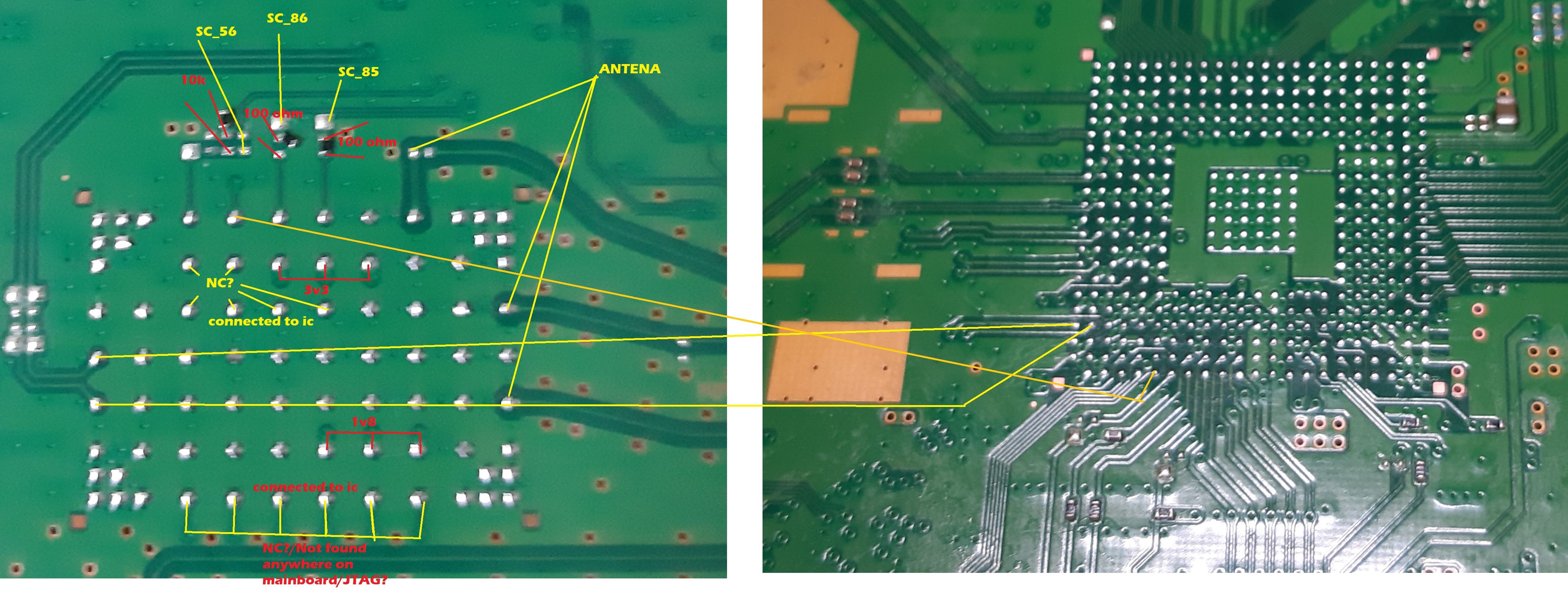
| 56 | 5 | P52/EX10 | WIFI_CTRL | ←I/O→ | 10k resistor to GND, and to wifi/BT module. See: wifi/BT 10x7 pinout or wifi/BT 9x7 pinout | Variable V Standby 3.3V Running |
| 57 | 5 | P53/EX11 | SC_RX | ←I/O→ | Syscon UART. Connected to service connector ? | |
| 58 | 5 | P54/EX12 | SC_TX | ←I/O→ | Syscon UART. Connected to service connector ? | Variable V Standby 3.3V Running |
| 59 | 5 | P55/EX13 | ←I/O→ | 3.3V Running | ||
| 60 | 5 | P56/EX14 | ←I/O→ | 3.3V Running | ||
| 61 | 5 | P57/EX15 | ←I/O→ | 3.3V Running | ||
| 62 | 1 | P17/EX31/TI02/TO02 | ←I/O→ | Connected to a voltage regulator ? | 1.5V Running | |
| 63 | 1 | P16/EX30/TI01/TO01/INTP5 | ←I/O→ | 0.8V Running | ||
| 64 | 1 | P15/EX29/RTCDIV/RTCCL | ←I/O→ | 1.5V Running | ||
| 65 | 1 | P14/EX28/RxD3 | ←I/O→ | 1.5V Running | ||
| 66 | 1 | P13/EX27/TxD3 | ←I/O→ | 1.5V Running | ||
| 67 | 1 | P12/EX26/SO00/TxD0 | BE_SPI_DO ? | ←I/O→ | CELL SPI bus ? | 1.5V Running |
| 68 | 1 | P11/EX25/SI00/RxD0 | BE_SPI_DI ? | ←I/O→ | CELL SPI bus ? | |
| 69 | 1 | P10/EX24/SCK00 | BE_SPI_CLK ? | ←I/O→ | CELL SPI bus ? | |
| 70 | AVREF1 | - | 1.5V Running | |||
| 71 | 11 | P110/ANO0 | ←I/O→ | Connected to a testpad | ||
| 72 | 11 | P111/ANO1 | ←I/O→ | 1.5V Running | ||
| 73 | AVREF0 | - | 1.20V Running | |||
| 74 | AVSS | GND | - | |||
| 75 | 15 | P157/ANI15 | ←I/O→ | 1.20V Running | ||
| 76 | 15 | P156/ANI14 | ←I/O→ | Resistor to GND ? | 1.20V Running | |
| 77 | 15 | P155/ANI13 | NOT_CONNECTED ? | ←I/O→ | ||
| 78 | 15 | P154/ANI12 | NOT_CONNECTED ? | ←I/O→ | ||
| 79 | 15 | P153/ANI11 | NOT_CONNECTED ? | ←I/O→ | 1.20V Running | |
| 80 | 15 | P152/ANI10 | NOT_CONNECTED ? | ←I/O→ | Variable V Standby 1.20V Running | |
| 81 | 15 | P151/ANI9 | ←I/O→ | POW_SW_DET ? | ||
| 82 | 15 | P150/ANI8 | ←I/O→ | To a testpad | Variable V Standby | |
| 83 | 2 | P27/ANI7 | ←I/O→ | EJECT_SW_DET ? | 3.3V Standby 3.3V Running | |
| 84 | 2 | P26/ANI6 | ←I/O→ | To a testpad | ||
| 85 | 2 | P25/ANI5 | WIFI_DATA_1 | ←I/O→ | 10K resistor to GND, to testpad, and to 100ohms resistor to Wifi/BT module. See: wifi/BT 10x7 pinout or wifi/BT 9x7 pinout | |
| 86 | 2 | P24/ANI4 | WIFI_DATA_2 | ←I/O→ | 10K resistor to GND, to testpad, and to 100ohms resistor to Wifi/BT module. See: wifi/BT 10x7 pinout or wifi/BT 9x7 pinout | |
| 87 | 2 | P23/ANI3 | ←I/O→ | 3.3V Running | ||
| 88 | 2 | P22/ANI2 | ←I/O→ | |||
| 89 | 2 | P21/ANI1 | ←I/O→ | 3.3V Running | ||
| 90 | 2 | P20/ANI0 | ←I/O→ | 3.3V Standby 3.3V Running | ||
| 91 | 13 | P130 | ACDC_STBY ? | O→ | 3.3V Running | |
| 92 | 13 | P131/TI06/TO06 | ←I/O→ | Connected to a voltage regulator ? | 3.3V Running | |
| 93 | 0 | P04/SCK10/SCL10 | ←I/O→ | RSX SPI bus ? | 3.3V Running | |
| 94 | 0 | P03/SI10/RxD1/SDA10 | ←I/O→ | RSX SPI bus ? | 3.3V Running | |
| 95 | 0 | P02/SO10/TxD1 | ←I/O→ | RSX SPI bus ? | 3.3V Running | |
| 96 | 0 | P01/TO00 | ←I/O→ | Connected to HDMI controller ? | 1.5V Running | |
| 97 | 0 | P00/TI00 | ←I/O→ | |||
| 98 | 14 | P145/TI07/TO07 | FAN_PWM ? | ←I/O→ | 0.8V Running | |
| 99 | 14 | P144/SO20/TxD2 | ←I/O→ | 3.3V Running | ||
| 100 | 14 | P143/SI20/RxD2/SDA20 | ←I/O→ | Connected to HDMI controller, and related with pin#1 ? | ||