Syscon Hardware: Difference between revisions
m (→Retail) |
(→PS3 Syscon models: Width reductions) |
||
| (47 intermediate revisions by 2 users not shown) | |||
| Line 1: | Line 1: | ||
<div style="float:right">[[File: | <div style="float:right">[[File:Syscon CXR713120-203GB DIE (detail).jpg|300px|thumb| Syscon CX'''R7131'''20-203GB DIE (detail)]]<br />[[File:Pyramid Syscon live probing.jpg|300px|thumb|Pyramid Syscon live probing]]</div> | ||
= Description = | |||
The PS3 syscon is the main power controller chip of the PS3. It is responsible for powering up the main 12v rail of the [[Power Supply]] and various power systems by switching different [[Talk:Regulators|voltage regulators]] in the motherboard, and for configuring and initialising the [[CELL BE|BE]], [[RSX]] and [[South Bridge|SB]] via dedicated SPI buses<br> | |||
The leds and buttons of the [[Switch boards|Switch board]] are connected to syscon, as well as the [[Cooling|fan/s]], buzzer, etc...<br> | |||
The Syscon is a SoC and based on a ARM7TDMI-S (in the [[Mullion]] syscons) or a NEC 78K0R (in the [[Sherwood]] syscons) design. There is external access by "JTAG" (disabled from factory on retail models), an EEPROM programming interface (only on Mullion) and Serial (UART). | |||
= | == PlayStation system controllers == | ||
== | {| class="wikitable" | ||
! Production Start Date (<=) || PS2 Mechacon !! PSP Syscon !! PS3 Syscon !! PSVita Syscon !! PS4 Syscon !! Used IC/CPU Core | |||
|- | |||
| <abbr title="GH-001+">10/1999</abbr> || CXP101064 || - || - || - || - || rowspan="2" | Sony SPC970 (100 pin) | |||
|- | |||
| <abbr title="GH-003+">01/2000</abbr> || CXP102064 || - || - || - || - | |||
|- | |||
| <abbr title="GH-015+">09/2000</abbr> || CXP103049 || - || - || - || - || Sony SPC??? (136 pin) | |||
|- bgcolor="#CCCCCC" | |||
| colspan="7" | | |||
|- | |||
| <abbr title="TMU-001, TMU-002, TA-079, TA-081">08/2004</abbr> || - || BAR''xx'' || - || - || - || NEC <abbr title="D790019">D780032AY</abbr> (78K0/78003xA, 64 pin) | |||
|- | |||
| <abbr title="TA-082, TA-086">07/2005</abbr> || - || B30''x'' || - || - || - || NEC <abbr title="D79F0036">D78F0531</abbr> (78K0/KE2 V2.00, 64 pin) | |||
|- | |||
| <abbr title="TA-085, TA-088, TA-091, TA-094">07/2007</abbr> || - || B40''x'' / 40''xx'' || - || - || - || NEC <abbr title="D79F????">D78F0544</abbr> (78K0/KF2 V2.00, 84 pin) | |||
|- | |||
| <abbr title="TA-090, TA-092, TA-093, TA-095, TA-096, TA-097">07/2008</abbr> || - || 3''xxx'' || - || - || - || NEC <abbr title="D79F????">D78F0534</abbr> (78K0/KE2 V2.00, 64 pin) | |||
|- | |- | ||
|- bgcolor="#CCCCCC" | |||
| colspan="7" | | |||
|- | |- | ||
| <abbr title="GH-023+, XPD-001, XPD-005">03/2003</abbr> || CXR706080 || - || - || - || - || rowspan="3" | Sony SR11 (ARM7TDMI)<br>PS2 (''Dragon''): 164 pin<br>PS3 (''Donkey''): 200 pin | |||
|- | |- | ||
| | | <abbr title="GH-032+">09/2004</abbr> || CXR716080 || - || CXR713120 || - || - | ||
|- | |- | ||
| | | <abbr title="GH-061+">07/2007</abbr> || CXR726080 || - || CXR714120 || - || - | ||
|- bgcolor="#CCCCCC" | |||
| colspan="7" | | |||
|- | |- | ||
| | | 03/2008 || - || - || SW || - || - || NEC <abbr title="D79F0073">D78F11AA</abbr> (78K0R/KH3 V3.40, 128 pin) | ||
|- | |- | ||
| | | 05/2009 || - || - || SW2 || - || - || NEC <abbr title="D79F0086">D78F11BB</abbr> (78K0R/KH3 V1.00, 128 pin) | ||
|- | |- | ||
| | | <abbr title="IRT-001, IRT-002, IRS-002, IRS-1001, DOL-1001, DOL-1002">07/2010</abbr> || - || - || - || <abbr title="No official name">"SC"</abbr> || - || NEC <abbr title="No/Matching internal name">D79F0109</abbr> (<abbr title="Mix between 78K0R/KH3 and 78K0R/Kx3-L">78K0R/KH3-L</abbr> V1.00, 121 pin) | ||
|- | |- | ||
| | | 06/2011 || - || - || SW3 || - || - || NEC <abbr title="D79F0123">D78F11CC</abbr> (78K0R/KG3 V1.00, 100 pin) | ||
|- | |- | ||
| | |- bgcolor="#CCCCCC" | ||
| colspan="7" | | |||
| | |||
|- | |- | ||
| | | <abbr title="CVN-001, SAA-001, SAB-001">07/2013</abbr> || - || - ||- || - || C0L || Renesas R5F100PL (RL78/G13 V3.03, 100 pin) | ||
|- | |||
|- | |- | ||
| | | <abbr title="USS-1001, USS-1002">08/2013</abbr> || - || - ||- || A0''xxx'' || - || Renesas R5F1ZCRK (RL78/G13 V3.03, 121 pin) | ||
|- | |- | ||
| | | <abbr title="SAC-001, SAD-001, SAD-002, SAD-003, SAE-001, SAE-002, SAE-003, SAE-004, SAF-004, SAF-006, HAC-001, NVA-001, NVB-003, NVB-004, NVG-001, NVG-002">04/2015</abbr> || - || - ||- || - || C0L2 || Renesas R5F101LL (RL78/G13 V3.03, 64 pin) | ||
|- | |- | ||
| [[ | |} | ||
* The SPC900 core was designed by Texas Instruments ([https://www.linkedin.com/in/hirakawa-katsunobu-55b09b2]) | |||
* ''CXP101064'', ''CXP102064'' are similar to CXP97 (''CXP971000'', ''CXP972032'', '''CXP973064''', ''CXP973F064''), the ''CXP103049'' matches no COTS because of its OCD support | |||
** In-Circuit-Emulator: Mitek NICE-SPC970 ([http://www.hitechfacility.co.jp/details.php?id=E0001913]); Debug software: SVD970; Flash programmer: SFP-2 | |||
* A ''F'' inside the model name specifies that the IC contains flash memory. | |||
** Mass-produced CXR/SW units don't have/use program flash memory for updates, instead an encrypted firmware patch is stored on the data-"EEPROM" | |||
* CXR7 series uses Sony SR11 CPU (ARM7TDMI) | |||
** Models with public datasheet: ''CXR702080'', ''CXR702F080'', ''CXR704060'' (datasheet: [http://www.alldatasheet.com/datasheet-pdf/pdf/294279/SONY/CXR704060.html 1]) | |||
* Prototype PS3 Syscon's: | |||
** [[CXR713F120A]] Syscon used on (early) pre-release prototypes, e.g. [[CEB-2030]], [[DECR-1000]], [[DEH-H1001-D]], [[DEH-H1000A-E]] | |||
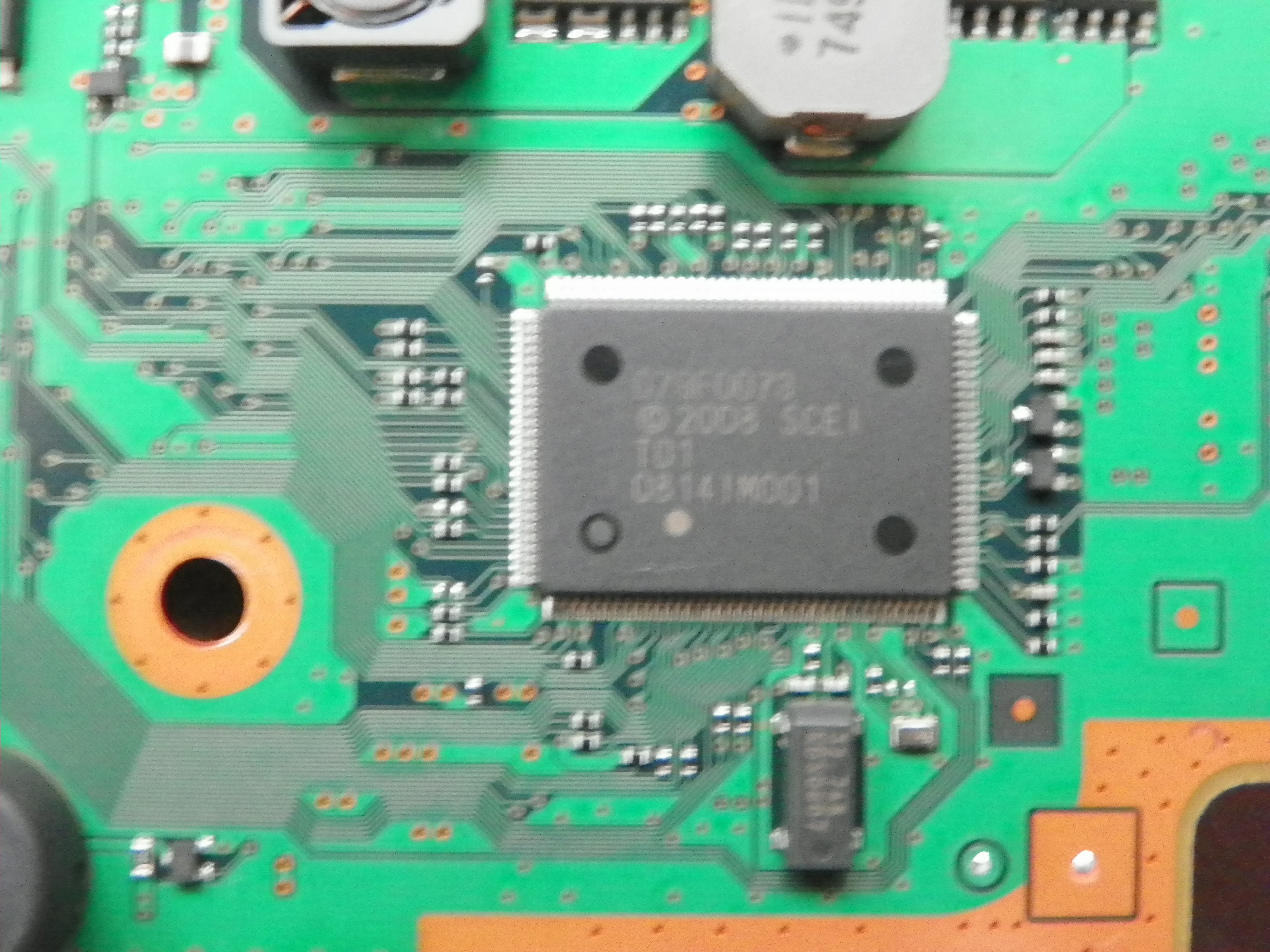
** [[DEH-FH1500J-A]] with [[VERTIGO-02]] board and SW series prototype ''[[Media:DEH-FH1500J-A_-_VERTIGO-02_-_Syscon_Hardware.jpg|D79F0073]]'' | |||
** [[CBEH-H2001]] with [[SUR-00x#SURTEES-03|SURTEES-03]] board and SW2 series prototype ''D79F0086'' | |||
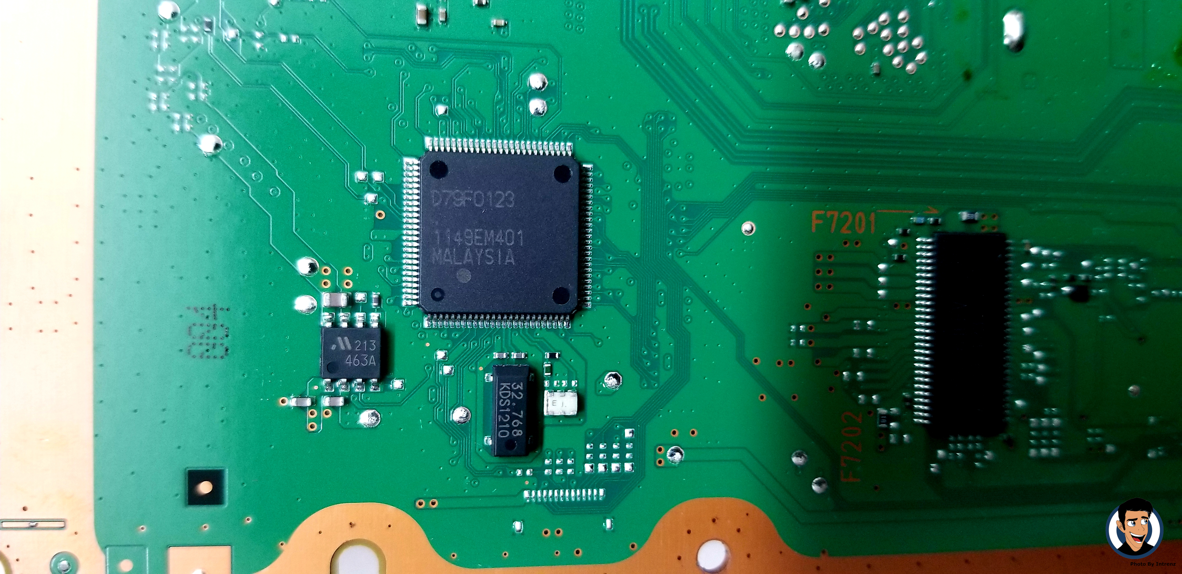
** [[DEH-ML00AK-G]] with MPX-001 (Prototype) board and SW3 series prototype ''[[Media:DEH-ML00AK-G_Board_4.jpg|D79F0123]]'' | |||
= PS3 Syscon models = | |||
{| class="wikitable" style="font-size:small;" | |||
|+ [[Mullion]] Syscons | |||
! colspan=9 | [[Syscon Hardware|Syscon]] !! rowspan="11" | !! colspan=8 | [[SKU Models|PS3 model]] & [[Motherboard Revisions|Motherboard]] compatibility by [[Platform ID]] !! rowspan=3 | Notes | |||
|- | |- | ||
| [[ | ! style="width:115px" rowspan=2 | Model !! colspan="3" rowspan=2 | [[System Controller Firmware|Rev. / Ver.]] / <abbr title="Syscon firmware build date">Year</abbr> !! rowspan=2 | Package !! colspan=4 | Memory !! [[SKU Models Nonretail|Prototypes<br>Non-retail]] !! [[DECR-1000]] !! [[CECHAxx]]<br>[[CECHBxx]] !! [[CECHCxx]]<br>[[CECHExx]] !! [[CECHGxx]] !! [[CECHHxx]] !! [[CECHJxx]]<br>[[CECHKxx]] !! [[DECR-1400]] | ||
|- | |- | ||
| [[ | ! style="width:40px" | ROM !! FLASH !! EEPROM !! RAM !! [[MPU-501]]<br>[[COOKIE-13]]<br>[[COK-001 (Prototype)|COK Proto]] !! [[TMU-520]] !! [[COK-001]] !! [[COK-002]] !! [[SEM-001]] !! [[DIA-001]] !! [[DIA-002]] !! [[DEB-001]] | ||
|- | |- | ||
! [[CXR713F120A]] | |||
| <abbr title="Depends of the syscon firmware version installed in it">ANY</abbr> || style="width:55px" | <abbr title="Depends of the syscon firmware version installed in it">ANY</abbr> || <abbr title="Depends of the syscon firmware version installed in it">ANY</abbr> || rowspan="8" style="width:60px" | [[Template:Syscon pinout BGA 200 pads|BGA 200]] || 128KB || 384KB || rowspan=4 | 32KB || rowspan=8 | 64KB || {{yes}}, factory || {{yes}}, factory || {{YES}} || {{YES}} || {{YES}} || {{YES}} || {{YES}} || {{YES}} || | |||
|- | |- | ||
! [[CXR713120-201GB]] | |||
| 0B8E || v1.0.0_k1 || 2006 || rowspan=7 | 384KB || rowspan=7 style="text-align:center; background:lightgrey;" | N/A || {{YES}} ? || {{YES}} ? || {{yes}}, factory || {{no}} || {{no}} || {{no}} || {{no}} || {{no}} || [[SC EEPROM|EEPROM Layout]] "cookie old". [[Syscon Thermal Config|Thermal config]] format 1 | |||
|- | |- | ||
! [[CXR713120-202GB]] | |||
| 0C16 || v1.1.3_k1 || 2006 || {{YES}} ? || {{YES}} ? || {{YES}} || {{yes}}, factory || {{no}} || {{no}} || {{no}} || {{no}} || [[SC EEPROM|EEPROM Layout]] "cookie old". [[Syscon Thermal Config|Thermal config]] format 1 | |||
|- | |- | ||
! [[CXR713120-203GB]] | |||
| 0D52 || v1.2.3_k1 || 2007 || {{YES}} ? || {{YES}} ? || {{YES}} || {{YES}} || {{yes}}, factory || {{no}} || {{no}} || {{no}} || [[SC EEPROM|EEPROM Layout]] "cookie new" ?. [[Syscon Thermal Config|Thermal config]] format 2 | |||
|- | |- | ||
! [[CXR714120-301GB]] | |||
| 0DBF || v1.3.3_k1 || 2007 || rowspan=4 | 20KB || {{YES}} ? || {{YES}} ? || {{YES}} || {{yes}}, <abbr title="Found in a CECHE01 MG (Metal Gear Solid 4 edition)">rare</abbr> || {{yes}}, factory || {{yes}}, factory || {{no}} || {{no}} || [[SC EEPROM|EEPROM Layout]] "cookie new". [[Syscon Thermal Config|Thermal config]] format 2 | |||
|- | |- | ||
! [[CXR714120-302GB]] | |||
| 0E69 || v1.4.4_k2 || 2007 || {{YES}} ? || {{YES}} ? || {{YES}} || {{YES}} || {{YES}} || {{YES}} || {{yes}}, factory || {{yes}}, factory || [[SC EEPROM|EEPROM Layout]] "cookie new". [[Syscon Thermal Config|Thermal config]] format 2 | |||
|- | |- | ||
! [[CXR714120-303GB]] | |||
| 0F29 || v1.5.0_k2 || 2009 || {{YES}} ? || {{YES}} ? || {{YES}} || {{yes}}, <abbr title="Found in a refurbished CECHCxx/COK-002 with a 65nm RSX">refurb</abbr> || {{YES}} || {{YES}} || {{YES}} || {{YES}} || [[SC EEPROM|EEPROM Layout]] "cookie new". [[Syscon Thermal Config|Thermal config]] format 2 | |||
|- | |- | ||
! [[CXR714120-304GB]] | |||
| 0F38 || v1.5.1_k2 || 2010 || {{YES}} ? || {{YES}} ? || {{yes}}, <abbr title="Found in a refurbished CECHAxx/COK-001 with a 40nm RSX">refurb</abbr> || {{YES}} || {{YES}} || {{YES}} || {{YES}} || {{YES}} || [[SC EEPROM|EEPROM Layout]] "cookie new". [[Syscon Thermal Config|Thermal config]] format 2 | |||
|} | |} | ||
== | {| class="wikitable" style="font-size:small;" | ||
|+ [[Sherwood]] Syscons | |||
! colspan=9 | [[Syscon Hardware|Syscon]] !! rowspan="13" | !! colspan=10 | [[SKU Models|PS3 model]] & [[Motherboard Revisions|Motherboard]] compatibility by [[Platform ID]] !! rowspan=3 | Notes | |||
|- | |||
! style="width:115px" rowspan=2 | Model !! colspan="3" rowspan=2 | [[System Controller Firmware|Rev. / Ver.]] / <abbr title="Syscon firmware build date">Year</abbr> !! rowspan=2 | Package !! colspan=4 | Memory !! [[SKU Models Nonretail|Prototypes<br>Non-retail]] !! [[CECHLxx]]<br />[[CECHMxx]]<br />[[CECHPxx]]<br />[[CECHQxx]] || [[CECH-20xx]] !! [[CECH-21xx]] !! [[CECH-25xx]] !! [[CECH-30xx]] !! [[CECH-40xx]] !! ? !! [[CECH-42xx]] !! [[CECH-43xx]] | |||
|- | |||
! style="width:40px" | ROM !! FLASH !! EEPROM !! RAM || [[VERTIGO-02|VERTIGO]] || [[VER-001]] || [[DYN-001]] !! [[SUR-001]] !! [[JTP-001]]<br>[[JSD-001]] !! [[KTE-001]] !! [[MSX-001]]<br>[[MPX-001]] !! [[NPX-001]] !! [[PPX-001]]<br>[[PQX-001]] || [[RTX-001]]<br>[[REX-001]] | |||
|- | |- | ||
! [[ | ! [[Media:DEH-FH1500J-A_-_VERTIGO-02_-_Syscon_Hardware.jpg|D79F0073]] | ||
| 0658 || style="width:55px" | <abbr title="Please help wiki by reporting this ID"><span style="background:#ff4444; color:#ffff00;">'''?.??.?'''</span></abbr> || 2008 || rowspan=6 style="width:60px" | [[Template:Syscon pinout LQFP 128 pins|LQFP 128]] || rowspan=10 style="text-align:center; background:lightgrey;" | N/A || rowspan=3 | 512KB || rowspan=10 style="text-align:center; background:lightgrey;" | N/A || rowspan=10 | 50KB || {{yes}}, factory || {{YES}} || {{YES}} ? || {{YES}} ? || {{YES}} ? || colspan="5" rowspan=6 style="text-align:center; background:lightgrey;" | No (different package) || | |||
|- | |- | ||
! [[SW-301]] | |||
| 065D || 0.17.0 || 2008 || {{YES}} ? || {{yes}}, factory || {{no}} || {{no}} || {{no}} || | |||
|- | |- | ||
! [[SW-302]] | |||
| <abbr title="Please help wiki by reporting this ID"><span style="background:#ff4444; color:#ffff00;">'''????'''</span></abbr> || <abbr title="Please help wiki by reporting this ID"><span style="background:#ff4444; color:#ffff00;">'''?.??.?'''</span></abbr> || 2008 || {{YES}} ? || {{yes}}, factory || {{no}} || {{no}} || {{no}} || | |||
|- | |- | ||
! [[SW2-301]] | |||
| 0832 || 1.11.0 || 2009 | |||
| rowspan=7 | 768KB || {{YES}} ? || {{YES}} ? || {{yes}}, factory || {{no}} || {{no}} || | |||
|- | |- | ||
! [[SW2-302]] | |||
| 08A0 || 1.16.0 || 2009 ||{{YES}} ? || {{YES}} ? || {{YES}} || {{yes}}, factory || {{no}} || | |||
|- | |- | ||
! [[SW2-303]] | |||
| 08C2 || 1.21.0 || 2010 || {{YES}} ? || {{YES}} ? || {{YES}} || {{YES}} || {{yes}}, factory || | |||
|- | |- | ||
! [[SW3-301]] | |||
| 0918 || 2.3.0 || 2011 || rowspan=4 | [[Template:Syscon pinout LQFP 100 pins|LQFP 100]] || colspan="5" rowspan=4 style="text-align:center; background:lightgrey;" | No (different package) || {{yes}}, factory || {{no}} || {{no}} || {{no}} || {{no}} || | |||
|- | |- | ||
! [[SW3-302]] | |||
| 098F || 2.12.0 || 2012 || {{YES}} || {{yes}}, factory || {{yes}}, factory || {{no}} || {{no}} || | |||
|- | |- | ||
! [[SW3-303]] | |||
| <abbr title="Please help wiki by reporting this ID"><span style="background:#ff4444; color:#ffff00;">'''????'''</span></abbr> || <abbr title="Please help wiki by reporting this ID"><span style="background:#ff4444; color:#ffff00;">'''?.??.?'''</span></abbr> || 2013 || ? || ? || ? || ? || ? || | |||
|- | |- | ||
! [[SW3-304]] | |||
| 09A4 || 2.21.0 || 2013 || {{YES}} || {{YES}} || {{YES}} || {{yes}}, factory || {{yes}}, factory || | |||
|} | |} | ||
| Line 163: | Line 223: | ||
| 0x17 || '''tmpforcp <zone ID>''' || Reference Tool's temperature For Communication Processor || Gets the temperature of reference tool | | 0x17 || '''tmpforcp <zone ID>''' || Reference Tool's temperature For Communication Processor || Gets the temperature of reference tool | ||
|- | |- | ||
| 0x18 || rowspan=" | | 0x18 || rowspan="8" colspan="3" style="background:lightgrey; color:#ff0000; text-align: center;" | Invalid CMDs | ||
|- | |- | ||
| 0x19 | | 0x19 | ||
| Line 172: | Line 232: | ||
|- | |- | ||
| 0x1C | | 0x1C | ||
|- | |||
| 0x1D | |||
|- | |- | ||
| 0x1E | | 0x1E | ||
| Line 200: | Line 262: | ||
! Packet ID !! Command/Action !! Logs !! Notes | ! Packet ID !! Command/Action !! Logs !! Notes | ||
|- | |- | ||
| 0x00 || '''version''' || | | 0x00 || '''version''' || version\nv1.0.4_c2\n (END) || | ||
|- | |- | ||
| 0x01 || '''bringup''' || | | 0x01 || '''bringup''' || (END) || | ||
|- | |- | ||
| 0x02 || '''shutdown''' || | | 0x02 || '''shutdown''' || Do nothing. (PowerOff State)\n (END) || Returns (END) if the system is on | ||
|- | |- | ||
| 0x03 || '''firmud''' || | | 0x03 || '''firmud''' || Start...\nErase User Program Area\n (END) || This will brick your SYSCON if you don't feed it any argument or feed to it the wrong argument! | ||
|- | |- | ||
| 0x04 || '''bsn''' || | | 0x04 || '''bsn''' || bsn\nNANNNNNNNNNA\n (END) || N is digit and A is char (removed for privacy) | ||
|- | |- | ||
| 0x05 || '''halt''' || | | 0x05 || '''halt''' || halt\n (END) || | ||
|- | |- | ||
| 0x06 || '''cp ready''' || | | 0x06 || '''cp ready''' || cp ready\nCP READY: OK\n (END) || | ||
|- | |- | ||
| 0x07 || '''cp busy''' || | | 0x07 || '''cp busy''' || cp ready\nCP BUSY: OK\n (END) || STATUS light blinks forever | ||
|- | |- | ||
| 0x08 || '''cp reset''' || No response || Should reset CP to factory settings | | 0x08 || '''cp reset''' || No response || Should reset CP to factory settings | ||
|- | |- | ||
| 0x09 || '''bestat''' || | | 0x09 || '''bestat''' || (PowerOff State)\n (END) || | ||
|- | |- | ||
| 0x0A || '''powersw''' || | | 0x0A || '''powersw''' || (END) || | ||
|- | |- | ||
| 0x0B || '''resetsw''' || | | 0x0B || '''resetsw''' || (END) || | ||
|- | |- | ||
| 0x0C || '''bootbeep stat''' || | | 0x0C || '''bootbeep stat''' || BOOT BEEP: ON\n (END) || when it's off BOOT BEEP status changes to OFF | ||
|- | |- | ||
| 0x0D || '''bootbeep on''' || | | 0x0D || '''bootbeep on''' || BOOT BEEP ON: DONE\n (END) || | ||
|- | |- | ||
| 0x0E || '''bootbeep off''' || | | 0x0E || '''bootbeep off''' || BOOT BEEP OFF: DONE\n (END) || | ||
|- | |- | ||
| 0x0F || '''Reset syscon''' || || | | 0x0F || '''Reset syscon''' || || | ||
|- | |- | ||
| 0x10 || '''xdrdiag info''' || | | 0x10 || '''xdrdiag info''' || 32\n (END) || | ||
|- | |- | ||
| 0x11 || '''xdrdiag start''' || | | 0x11 || '''xdrdiag start''' || DIAG START\n (END) || | ||
|- | |- | ||
| 0x12 || '''xdrdiag result''' || | | 0x12 || '''xdrdiag result''' || XDR OK\n (END) || will return ERROR NOT STARTED if xdrdiag start wasn't run previously | ||
|- | |- | ||
| 0x13 || '''xiodiag''' || | | 0x13 || '''xiodiag''' || 0 903\n (END) || | ||
|- | |- | ||
| 0x14 || '''fandiag''' || | | 0x14 || '''fandiag''' || ERROR FAN ACTIVE\n (END) || | ||
|- | |- | ||
| 0x15 || '''errlog''' || | | 0x15 || '''errlog''' || ofst[ %d]:err_code:0x%08X, clock:0x%08X YYYY/MM/DD HH:MM:SS || bunch of error logs. ends with (END) once they're over | ||
|- | |- | ||
| 0x16 || '''Read line''' || || | | 0x16 || '''Read line''' || || | ||
| Line 248: | Line 310: | ||
| 0x17 || '''tmpforcp <zone ID>''' || | | 0x17 || '''tmpforcp <zone ID>''' || | ||
|- | |- | ||
| 0x20 || '''cp beepremote''' || | | 0x20 || '''cp beepremote''' || (END) || | ||
|- | |- | ||
| 0x21 || '''cp beep2kn1n3''' || | | 0x21 || '''cp beep2kn1n3''' || (END) || sends a beep different than SYSCON beep :) | ||
|- | |- | ||
| 0x22 || '''cp beep2kn2n3''' || | | 0x22 || '''cp beep2kn2n3''' || (END) || sends two beeps different than SYSCON beeps :) | ||
|- | |- | ||
| ?? || '''csum''' || | | rowspan="8" | ?? || rowspan="8" | '''csum''' || Checksum: [027460C9] [68269779] [C19A855E]\n (END) || displays 3 hexadecimal numbers inside rect parenthesis. the numbers are always the same, except when syscon version changes (v1.0.5_c1) | ||
|- | |- | ||
| | | Checksum: [02746F91] [682F04DA] [27688CF5]\n (END) || Another response (v1.0.4_c2) | ||
|- | |- | ||
| | | Checksum: [0274C877] [684DA659] [EA426BB1]\n (END) || Another response (v1.0.4_c1) | ||
|- | |- | ||
| | | Checksum: [027B4064] [6B450C64] [4FBF6DA3]\n (END) || Another response (v1.0.3_c1) | ||
|- | |- | ||
| | | Checksum: [027E1B71] [6CDA9F25] [E0C67065]\n (END) || Another response (v1.0.1_c1) | ||
|- | |- | ||
| | | Checksum: [02812855] [6E83917C] [D40F70A5]\n (END) || Another response (v0.9.14_c1) | ||
|- | |- | ||
| | | Checksum: [02835059] [6FC5C632] [BB9BBEC3]\n (END) || Another response (v0.9.9_c1) | ||
|- | |- | ||
| | | Checksum: [026F7951] [66CB09FF] [4EA06B56]\n (END) || Another response (v0.8.4_c8) | ||
|- | |- | ||
| ?? || '''osbo''' || | | ?? || '''osbo''' || done\n (END) || | ||
|- | |- | ||
| ?? || '''scopen''' || | | ?? || '''scopen''' || SC_READY\nERROR 1\n\n*** Invalid Argument ***\n\n[mullion]$ || | ||
|- | |- | ||
| ?? || '''scclose''' || | | ?? || '''scclose''' || \n\n\nSC_SUCCESS\n\n[mullion]$ || | ||
|- | |- | ||
|} | |} | ||
| Line 334: | Line 396: | ||
== Syscon UART == | == Syscon UART == | ||
{| class="wikitable" | {| class="wikitable" | ||
! BGA !! Name !! Description | ! BGA !! Name !! Description | ||
| Line 344: | Line 405: | ||
|} | |} | ||
<gallery> | |||
File:COK-001 SC UART testpads.jpg|[[COK-001]] SC UART testpads | |||
File:COK-002 SC UART testpads.jpg|[[COK-002]] SC UART testpads | |||
File:SEM-001 SC UART testpads.jpg|[[SEM-001]] SC UART testpads | |||
File:DIA-001 SC UART testpads.jpg|[[DIA-001]] SC UART testpads | |||
File:DIA-002 SC UART testpads.jpg|[[DIA-002]] SC UART testpads | |||
File:VER-001 SC UART testpads.jpg|[[VER-001]] SC UART testpads | |||
File:DYN-001 SC UART testpads.jpg|[[DYN-001]] SC UART testpads | |||
File:SUR-001 SC and SB UART testpads.jpg|[[SUR-001]] SC and SB UART testpads | |||
File:JTP-001 SC and SB UART testpads.jpg|[[JTP-001]] SC and SB UART testpads | |||
File:JSD-001 SC and SB UART testpads.jpg|[[JSD-001]] SC and SB UART testpads | |||
File:KTE-001 SC and SB UART testpads.jpg|[[KTE-001]] SC and SB UART testpads | |||
File:SW3 SC UART testpads.jpg|SW3 SC UART testpads | |||
</gallery> | |||
You can attach a 3.3v TTL cable (LV-TTL) to the UART on syscon (UART0_TxD, UART0_RxD). Baud rate is 57600. There is a simple plaintext protocol involved. This varies on different syscon models. Example: | |||
'''<command>:<hash>''' | '''<command>:<hash>''' | ||
| Line 558: | Line 634: | ||
<!--// Remote Power ON/OFF (from network, HDMI CEC commands, etc...) is managed by devices connected to the southbridge (ethernet/wifi/BT, HDMI controller, etc...) //--> | <!--// Remote Power ON/OFF (from network, HDMI CEC commands, etc...) is managed by devices connected to the southbridge (ethernet/wifi/BT, HDMI controller, etc...) //--> | ||
= Testpads and alternative solder points = | |||
*The identification of the syscon UART testpads can be made by grouping the motherboard models in a similar way we was doing with the [[Teensy%2B%2B_2.0#Schematics_by_motherboard_.28retail.29| layouts]] of the hardware flashers, there are 7 retail testpads layouts: | |||
**Layout 1 = COK-001, COK-002 (fat, mullion, NAND) | |||
**Layout 2 = SEM-001 (fat, mullion, NAND) | |||
**Layout 3 = DIA-001, DIA-002 (fat, mullion, NOR) | |||
**Layout 4 = VER-001 (fat, sherwood, NOR) | |||
**Layout 5 = DYN-001 (slim, sherwood, NOR) | |||
**Layout 6 = SUR-001, JTP-001, JSD-001, KTE-001 (slim, sherwood, NOR) | |||
**Layout 7 = MSX-001, MPX-001, NPX-001, PPX-001, PQX-001, RTX-001, REX-001 (superslim, sherwood, NOR/eMMC) | |||
== DIA-001 and DIA-002 == | |||
This points are availables to intercept signals by soldering wires, attaching probes, osciloscopes, etc... The photos are only orientatives to follow the traces, there's no need to remove the SYSCON to intercept this signals so can be done while its working | |||
All this points has been hardware reverse engineered from a [[CECHHxx|CECHH02]]/[[DIA-00x#DIA-001|DIA-001]] motherboard | |||
{{clear}} | |||
=== Topside Pinout === | |||
<div style="float:right">[[File:syscon_top.jpg|thumbnail|Syscon Top Pinouts<br />[[CECHHxx|CECHH02]]/[[DIA-00x#DIA-001|DIA-001]]]]</div> | |||
{|class="wikitable" | |||
! Pin # | |||
! Name | |||
! Description | |||
|- | |||
!B3 | |||
|SW_10 | |||
|Unknown | |||
|- | |||
!A6 | |||
|MC_RESERVED2 | |||
|Unknown | |||
|- | |||
!E10 | |||
|MUL_CHKSTP_OUT | |||
|Unknown | |||
|- | |||
!C15 | |||
|VSS | |||
|Power Ground | |||
|- | |||
!B16 | |||
|OSCOUT | |||
|Goes to unpopulated crystal | |||
|- | |||
!C16 | |||
|OSCIN | |||
|From unpupulated crystal | |||
|- | |||
!B15 | |||
|POW_FAIL | |||
|Power Failure Signal | |||
|- | |||
!H1 | |||
|PN5 | |||
|Unknown | |||
|- | |||
!H2 | |||
|PN6 | |||
|Unknown | |||
|- | |||
!R1 | |||
|PM7 | |||
|Unknown | |||
|- | |||
!R2 | |||
|PM6 | |||
|Unknown | |||
|- | |||
!M4 | |||
|SW9 | |||
|Unknown | |||
|- | |||
!M10 | |||
|XDR_FET_SCK | |||
|Unknown | |||
|} | |||
=== Bottomside Pinout === | |||
<div style="float:right">[[File:DIA-001 SysCon EPROM Interface.png|thumbnail|[[DIA-001]] [[CECHHxx]] [[SC EEPROM]] Interface]]<br />[[File:syscon_bottom.jpg|thumbnail|Syscon Bottom Pinouts<br />[[CECHHxx|CECHH02]]/[[DIA-00x#DIA-001|DIA-001]]]]<br />[[File:Syscon uart soldered on dia-002.jpg|thumbnail|Syscon UART soldered<br />[[CECHJxx]]/[[CECHKxx]] [[DIA-00x#DIA-002|DIA-002]]]]</div> | |||
{|class="wikitable" | |||
! Pin # | |||
! Name | |||
! Description | |||
|- | |||
!R5 | |||
|VDD | |||
| +3.3v | |||
|- | |||
!R7 | |||
|DVDD | |||
| +1.8v | |||
|- | |||
!C15 | |||
|VSS | |||
|Power Ground | |||
|- | |||
!N16 | |||
|DIAG_MODE | |||
|Unknown | |||
|- | |||
!N15 | |||
|BACKUP_MODE | |||
|Unknown | |||
|- | |||
!P16 | |||
|UART0_TxD | |||
|Serial | |||
|- | |||
!P15 | |||
|UART0_RxD | |||
|Serial | |||
|- | |||
!R9 | |||
|PQ1 | |||
|Unknown | |||
|- | |||
!B12 | |||
|POW_SW | |||
|Power Switch | |||
|- | |||
!A12 | |||
|EJECT_SW | |||
|Eject Switch | |||
|- | |||
!L7 | |||
|JNTAST | |||
|JTAG | |||
|- | |||
!L8 | |||
|JRTCK | |||
|JTAG | |||
|- | |||
!L9 | |||
|JTMS | |||
|JTAG | |||
|- | |||
!K7 | |||
|JTDI | |||
|JTAG | |||
|- | |||
!K8 | |||
|JTCK | |||
|JTAG | |||
|- | |||
!K9 | |||
|JTDO | |||
|JTAG | |||
|- | |||
!M6 | |||
|SW_7_B | |||
|Unknown | |||
|- | |||
!M8 | |||
|FANPWM1 | |||
|Unknown | |||
|- | |||
!E5 | |||
|GX_VSRT | |||
|Unknown | |||
|- | |||
!B5 | |||
|DVE_RST | |||
|Unknown | |||
|- | |||
!G4 | |||
|HDMI_RST1 | |||
|Unknown | |||
|- | |||
!D4 | |||
|XDR_FET_RST | |||
|Unknown | |||
|} | |||
{{Motherboard Components}}<noinclude>[[Category:Main]]</noinclude> | {{Motherboard Components}}<noinclude>[[Category:Main]]</noinclude> | ||
Revision as of 20:12, 26 June 2021
.jpg)

Description
The PS3 syscon is the main power controller chip of the PS3. It is responsible for powering up the main 12v rail of the Power Supply and various power systems by switching different voltage regulators in the motherboard, and for configuring and initialising the BE, RSX and SB via dedicated SPI buses
The leds and buttons of the Switch board are connected to syscon, as well as the fan/s, buzzer, etc...
The Syscon is a SoC and based on a ARM7TDMI-S (in the Mullion syscons) or a NEC 78K0R (in the Sherwood syscons) design. There is external access by "JTAG" (disabled from factory on retail models), an EEPROM programming interface (only on Mullion) and Serial (UART).
PlayStation system controllers
| Production Start Date (<=) | PS2 Mechacon | PSP Syscon | PS3 Syscon | PSVita Syscon | PS4 Syscon | Used IC/CPU Core |
|---|---|---|---|---|---|---|
| 10/1999 | CXP101064 | - | - | - | - | Sony SPC970 (100 pin) |
| 01/2000 | CXP102064 | - | - | - | - | |
| 09/2000 | CXP103049 | - | - | - | - | Sony SPC??? (136 pin) |
| 08/2004 | - | BARxx | - | - | - | NEC D780032AY (78K0/78003xA, 64 pin) |
| 07/2005 | - | B30x | - | - | - | NEC D78F0531 (78K0/KE2 V2.00, 64 pin) |
| 07/2007 | - | B40x / 40xx | - | - | - | NEC D78F0544 (78K0/KF2 V2.00, 84 pin) |
| 07/2008 | - | 3xxx | - | - | - | NEC D78F0534 (78K0/KE2 V2.00, 64 pin) |
| 03/2003 | CXR706080 | - | - | - | - | Sony SR11 (ARM7TDMI) PS2 (Dragon): 164 pin PS3 (Donkey): 200 pin |
| 09/2004 | CXR716080 | - | CXR713120 | - | - | |
| 07/2007 | CXR726080 | - | CXR714120 | - | - | |
| 03/2008 | - | - | SW | - | - | NEC D78F11AA (78K0R/KH3 V3.40, 128 pin) |
| 05/2009 | - | - | SW2 | - | - | NEC D78F11BB (78K0R/KH3 V1.00, 128 pin) |
| 07/2010 | - | - | - | "SC" | - | NEC D79F0109 (78K0R/KH3-L V1.00, 121 pin) |
| 06/2011 | - | - | SW3 | - | - | NEC D78F11CC (78K0R/KG3 V1.00, 100 pin) |
| 07/2013 | - | - | - | - | C0L | Renesas R5F100PL (RL78/G13 V3.03, 100 pin) |
| 08/2013 | - | - | - | A0xxx | - | Renesas R5F1ZCRK (RL78/G13 V3.03, 121 pin) |
| 04/2015 | - | - | - | - | C0L2 | Renesas R5F101LL (RL78/G13 V3.03, 64 pin) |
- The SPC900 core was designed by Texas Instruments ([1])
- CXP101064, CXP102064 are similar to CXP97 (CXP971000, CXP972032, CXP973064, CXP973F064), the CXP103049 matches no COTS because of its OCD support
- In-Circuit-Emulator: Mitek NICE-SPC970 ([2]); Debug software: SVD970; Flash programmer: SFP-2
- A F inside the model name specifies that the IC contains flash memory.
- Mass-produced CXR/SW units don't have/use program flash memory for updates, instead an encrypted firmware patch is stored on the data-"EEPROM"
- CXR7 series uses Sony SR11 CPU (ARM7TDMI)
- Models with public datasheet: CXR702080, CXR702F080, CXR704060 (datasheet: 1)
- Prototype PS3 Syscon's:
- CXR713F120A Syscon used on (early) pre-release prototypes, e.g. CEB-2030, DECR-1000, DEH-H1001-D, DEH-H1000A-E
- DEH-FH1500J-A with VERTIGO-02 board and SW series prototype D79F0073
- CBEH-H2001 with SURTEES-03 board and SW2 series prototype D79F0086
- DEH-ML00AK-G with MPX-001 (Prototype) board and SW3 series prototype D79F0123
PS3 Syscon models
| Syscon | PS3 model & Motherboard compatibility by Platform ID | Notes | ||||||||||||||||
|---|---|---|---|---|---|---|---|---|---|---|---|---|---|---|---|---|---|---|
| Model | Rev. / Ver. / Year | Package | Memory | Prototypes Non-retail |
DECR-1000 | CECHAxx CECHBxx |
CECHCxx CECHExx |
CECHGxx | CECHHxx | CECHJxx CECHKxx |
DECR-1400 | |||||||
| ROM | FLASH | EEPROM | RAM | MPU-501 COOKIE-13 COK Proto |
TMU-520 | COK-001 | COK-002 | SEM-001 | DIA-001 | DIA-002 | DEB-001 | |||||||
| CXR713F120A | ANY | ANY | ANY | BGA 200 | 128KB | 384KB | 32KB | 64KB | Yes, factory | Yes, factory | YES | YES | YES | YES | YES | YES | ||
| CXR713120-201GB | 0B8E | v1.0.0_k1 | 2006 | 384KB | N/A | YES ? | YES ? | Yes, factory | No | No | No | No | No | EEPROM Layout "cookie old". Thermal config format 1 | ||||
| CXR713120-202GB | 0C16 | v1.1.3_k1 | 2006 | YES ? | YES ? | YES | Yes, factory | No | No | No | No | EEPROM Layout "cookie old". Thermal config format 1 | ||||||
| CXR713120-203GB | 0D52 | v1.2.3_k1 | 2007 | YES ? | YES ? | YES | YES | Yes, factory | No | No | No | EEPROM Layout "cookie new" ?. Thermal config format 2 | ||||||
| CXR714120-301GB | 0DBF | v1.3.3_k1 | 2007 | 20KB | YES ? | YES ? | YES | Yes, rare | Yes, factory | Yes, factory | No | No | EEPROM Layout "cookie new". Thermal config format 2 | |||||
| CXR714120-302GB | 0E69 | v1.4.4_k2 | 2007 | YES ? | YES ? | YES | YES | YES | YES | Yes, factory | Yes, factory | EEPROM Layout "cookie new". Thermal config format 2 | ||||||
| CXR714120-303GB | 0F29 | v1.5.0_k2 | 2009 | YES ? | YES ? | YES | Yes, refurb | YES | YES | YES | YES | EEPROM Layout "cookie new". Thermal config format 2 | ||||||
| CXR714120-304GB | 0F38 | v1.5.1_k2 | 2010 | YES ? | YES ? | Yes, refurb | YES | YES | YES | YES | YES | EEPROM Layout "cookie new". Thermal config format 2 | ||||||
| Syscon | PS3 model & Motherboard compatibility by Platform ID | Notes | ||||||||||||||||||
|---|---|---|---|---|---|---|---|---|---|---|---|---|---|---|---|---|---|---|---|---|
| Model | Rev. / Ver. / Year | Package | Memory | Prototypes Non-retail |
CECHLxx CECHMxx CECHPxx CECHQxx |
CECH-20xx | CECH-21xx | CECH-25xx | CECH-30xx | CECH-40xx | ? | CECH-42xx | CECH-43xx | |||||||
| ROM | FLASH | EEPROM | RAM | VERTIGO | VER-001 | DYN-001 | SUR-001 | JTP-001 JSD-001 |
KTE-001 | MSX-001 MPX-001 |
NPX-001 | PPX-001 PQX-001 |
RTX-001 REX-001 | |||||||
| D79F0073 | 0658 | ?.??.? | 2008 | LQFP 128 | N/A | 512KB | N/A | 50KB | Yes, factory | YES | YES ? | YES ? | YES ? | No (different package) | ||||||
| SW-301 | 065D | 0.17.0 | 2008 | YES ? | Yes, factory | No | No | No | ||||||||||||
| SW-302 | ???? | ?.??.? | 2008 | YES ? | Yes, factory | No | No | No | ||||||||||||
| SW2-301 | 0832 | 1.11.0 | 2009 | 768KB | YES ? | YES ? | Yes, factory | No | No | |||||||||||
| SW2-302 | 08A0 | 1.16.0 | 2009 | YES ? | YES ? | YES | Yes, factory | No | ||||||||||||
| SW2-303 | 08C2 | 1.21.0 | 2010 | YES ? | YES ? | YES | YES | Yes, factory | ||||||||||||
| SW3-301 | 0918 | 2.3.0 | 2011 | LQFP 100 | No (different package) | Yes, factory | No | No | No | No | ||||||||||
| SW3-302 | 098F | 2.12.0 | 2012 | YES | Yes, factory | Yes, factory | No | No | ||||||||||||
| SW3-303 | ???? | ?.??.? | 2013 | ? | ? | ? | ? | ? | ||||||||||||
| SW3-304 | 09A4 | 2.21.0 | 2013 | YES | YES | YES | Yes, factory | Yes, factory | ||||||||||||
Syscon Externalised Ports
Note: for more specific information per model, see the links to each subpage in the Serialnumbers per SKU table.
Syscon UART packets
SCUART daemon (SCUARTD) packet structure
SCUARTD packets includes header of 0x3 bytes and optional payload (depending on the command).
Packet IDs are not important, they are used only by clients and processed by SCUART daemon. SCUART daemon opens terminal file /dev/ttyS0 and use it to send commands and receive responses.
| Offset | Size | Description |
|---|---|---|
| 0x00 | 0x01 | Magic? |
| 0x01 | 0x01 | Payload size |
| 0x02 | 0x01 | Command |
| 0x03 | Payload size | Payload data |
Packets
| Packet ID | Command/Action | Description | Notes |
|---|---|---|---|
| 0x00 | version | Firmware version | Gets installed syscon's firmware version (Note: backup bank contains version 0.4.5_b4 !! On CEB-2030 it is 0.3.0 ) |
| 0x01 | bringup | Bring up | |
| 0x02 | shutdown | Shutdown | |
| 0x03 | firmud | Firmware update | Notifies about firmware update operation |
| 0x04 | bsn | Board Serial Number | Retrieves syscon's Board Serial Number |
| 0x05 | halt | Halt | Used at start of firmware update operation |
| 0x06 | cp ready | Communication Processor Ready | |
| 0x07 | cp busy | Communication Processor Busy | |
| 0x08 | cp reset | Communication Processor Reset | |
| 0x09 | bestat | Cell B.E. status | Retrieves Cell B.E. status |
| 0x0A | powersw | Power switch | toggles power switch button short pressing |
| 0x0B | resetsw | Reset switch | toggles reset switch button holding |
| 0x0C | bootbeep stat | Boot Beep Status | |
| 0x0D | bootbeep on | Boot Beep On | |
| 0x0E | bootbeep off | Boot Beep Off | |
| 0x0F | Reset syscon | Reset Syscon | Resets syscon |
| 0x10 | xdrdiag info | XDR diagnostics Information | |
| 0x11 | xdrdiag start | XDR diagnostics Start | Starts XDR diagnostics |
| 0x12 | xdrdiag result | XDR diagnostics Result | Gets a result of XDR diagnostics |
| 0x13 | xiodiag | XIO diagnostics | Starts XIO diagnostics and gets a result of it |
| 0x14 | fandiag | Fan diagnostics | Retrieves RPMs of fans |
| 0x15 | errlog | Error log | Retrieves a list of codes (with timestamps) of latest errors |
| 0x16 | Read line | Read Line | |
| 0x17 | tmpforcp <zone ID> | Reference Tool's temperature For Communication Processor | Gets the temperature of reference tool |
| 0x18 | Invalid CMDs | ||
| 0x19 | |||
| 0x1A | |||
| 0x1B | |||
| 0x1C | |||
| 0x1D | |||
| 0x1E | |||
| 0x1F | |||
| 0x20 | cp beepremote | Communication Processor Beep Remote | |
| 0x21 | cp beep2kn1n3 | ||
| 0x22 | cp beep2kn2n3 | ||
| ?? | csum | Checksum | Calculates the Checksum of something (No packet ID listing on scuartd) |
| ?? | osbo | ?Operating System Boot? | No idea what this does, but returns donewhen it's sent |
| ?? | scopen | Syscon Open | returns SC_READY or ERROR 1 |
| ?? | scclose | Syscon Close | ??? |
| ?? | ejectsw | Eject Switch | toggles eject switch button pressing (3 beeps) |
Packets Logs
| Packet ID | Command/Action | Logs | Notes |
|---|---|---|---|
| 0x00 | version | version\nv1.0.4_c2\n (END) | |
| 0x01 | bringup | (END) | |
| 0x02 | shutdown | Do nothing. (PowerOff State)\n (END) | Returns (END) if the system is on |
| 0x03 | firmud | Start...\nErase User Program Area\n (END) | This will brick your SYSCON if you don't feed it any argument or feed to it the wrong argument! |
| 0x04 | bsn | bsn\nNANNNNNNNNNA\n (END) | N is digit and A is char (removed for privacy) |
| 0x05 | halt | halt\n (END) | |
| 0x06 | cp ready | cp ready\nCP READY: OK\n (END) | |
| 0x07 | cp busy | cp ready\nCP BUSY: OK\n (END) | STATUS light blinks forever |
| 0x08 | cp reset | No response | Should reset CP to factory settings |
| 0x09 | bestat | (PowerOff State)\n (END) | |
| 0x0A | powersw | (END) | |
| 0x0B | resetsw | (END) | |
| 0x0C | bootbeep stat | BOOT BEEP: ON\n (END) | when it's off BOOT BEEP status changes to OFF |
| 0x0D | bootbeep on | BOOT BEEP ON: DONE\n (END) | |
| 0x0E | bootbeep off | BOOT BEEP OFF: DONE\n (END) | |
| 0x0F | Reset syscon | ||
| 0x10 | xdrdiag info | 32\n (END) | |
| 0x11 | xdrdiag start | DIAG START\n (END) | |
| 0x12 | xdrdiag result | XDR OK\n (END) | will return ERROR NOT STARTED if xdrdiag start wasn't run previously |
| 0x13 | xiodiag | 0 903\n (END) | |
| 0x14 | fandiag | ERROR FAN ACTIVE\n (END) | |
| 0x15 | errlog | ofst[ %d]:err_code:0x%08X, clock:0x%08X YYYY/MM/DD HH:MM:SS | bunch of error logs. ends with (END) once they're over |
| 0x16 | Read line | ||
| 0x17 | tmpforcp <zone ID> | ||
| 0x20 | cp beepremote | (END) | |
| 0x21 | cp beep2kn1n3 | (END) | sends a beep different than SYSCON beep :) |
| 0x22 | cp beep2kn2n3 | (END) | sends two beeps different than SYSCON beeps :) |
| ?? | csum | Checksum: [027460C9] [68269779] [C19A855E]\n (END) | displays 3 hexadecimal numbers inside rect parenthesis. the numbers are always the same, except when syscon version changes (v1.0.5_c1) |
| Checksum: [02746F91] [682F04DA] [27688CF5]\n (END) | Another response (v1.0.4_c2) | ||
| Checksum: [0274C877] [684DA659] [EA426BB1]\n (END) | Another response (v1.0.4_c1) | ||
| Checksum: [027B4064] [6B450C64] [4FBF6DA3]\n (END) | Another response (v1.0.3_c1) | ||
| Checksum: [027E1B71] [6CDA9F25] [E0C67065]\n (END) | Another response (v1.0.1_c1) | ||
| Checksum: [02812855] [6E83917C] [D40F70A5]\n (END) | Another response (v0.9.14_c1) | ||
| Checksum: [02835059] [6FC5C632] [BB9BBEC3]\n (END) | Another response (v0.9.9_c1) | ||
| Checksum: [026F7951] [66CB09FF] [4EA06B56]\n (END) | Another response (v0.8.4_c8) | ||
| ?? | osbo | done\n (END) | |
| ?? | scopen | SC_READY\nERROR 1\n\n*** Invalid Argument ***\n\n[mullion]$ | |
| ?? | scclose | \n\n\nSC_SUCCESS\n\n[mullion]$ |
Notes
- Some commands are unavailable on earlier firmwares, for example, tmpforcp is only supported on 1.3.3+.
- Some commands are divided into several strings, the first part (if exists) describes a command group, the second part describes the actual command and other parts describes command arguments.
- Real syscon commands have an ASCII form (a bold text in the 2nd column) instead of bytes above.
- Packet with ID *0x03* notifies syscon and calls SX program (based on ZMODEM protocol) to send firmware, syscon have custom or original implementation of RX program to receive firmware. An implementation of ZMODEM protocol used by Sony: http://oss.sony.net/Products/Linux/Others/Download/DECR-1000/mips_fp_le-lrzsz-0.12.20-devtool.1.src.rpm
A start of syscon's update procedure:
- A CP development tool includes several scripts which are participated in syscon update procedure. It starts after a CP update via update_syscon.pl perl script.
- This script checks the current syscon's firmware version. If it is in mask rom then it skips an update procedure, if not it checks major/minor/release parts of both versions and if a new version is applicable then it launches scfirmup utility and pass the firmware file path as an argument.
- scfirmup is a stupid tool which prepares a connection to SCUARTD and sends an update packet with a file path inside it. There is no need to comment it, here is reimplementation: http://pastie.org/private/6h8mfeoics4mdxear7ayg
A syscon's update operation in SCUARTD consists of following steps:
- 1. Check if SX program presents in /usr/bin/sx. It should be a regular file.
- 2. Check if specified firmware file is a regular file.
- 3. Halt syscon by sending command halt to UART, then wait some time until it prints HALT: OK.
- 4. Reset syscon by sending byte 0x30 to GPIO register SC_PI0_DIPSW, byte 0x30 to GPIO register SC_RSTX, waiting 1 second and writing byte 0x31 to GPIO register SC_RSTX.
- 5. Get current syscon's firmwave version by sending command version to UART. After receiving it, look for a character after the first _ (underscore) symbol from the left side of string and if it equals to the character b, then proceed to the next step, otherwise go to the (8) step. (It is possible to patch this step to allow upgrading or downgrading at will)
- 6. Prepare syscon for an update by sending command firmud to UART, then fork the current process; the current process won't finish until a message Done from UART arrives (it is the end of update operation).
- 7. In the forked process start SX program and pass firmware file path to it. SX program reads firmware file and transfer each chunk of it to syscon.
- 8. After successful update operation reset syscon (a different way) by sending byte 0x31 to GPIO register SC_PI0_DIPSW, byte 0x30 to GPIO register SC_RSTX, waiting 1 second and writing byte 0x31 to GPIO register SC_RSTX.
Notes:
- It seems all scuartds checks firmware revision and probably syscon is updated only once (after factory).
- To be able to reflash it you need to patch SCUARTD or do a manual update without the use of SCUARTD.
- You need to patch a single byte in SCUARTD to be able to flash any firmware (for example, to downgrade your syscon).
.text:00403A94: /* scuartd from CP 1.3.3 */
lb      $v1, 1($v0)
li      $v0, "b" /* 62 00 02 24 -> 63 00 02 24 */
bne     $v1, $v0, loc_4039F4
move    $a0, $zero
- An actual firmware update process (without halting and resetting steps) takes about 1 minute.
- You cannot install a corrupted firmware with scfirmup unless you corrupt the header! It seems there is a hash of sorts (possibly of the plaintext) in the header preventing scfirmup from installing something corrupt
- Updating SYSCON requires the DECR to be in standby mode! You cannot update it while it is on.
- Corrupting the header and the body will make firmup install the SYSCON update anyways! be careful not to do it!
- Should you brick SYSCON, here's a patch to "unbrick" it, do not use it unless you brick it though!
.text:004038C0:
lw      $a0, 4($s4)
li      $a1, 0x400000
nop
addiu   $a1, (aHalt - 0x400000)  # "halt"
la      $t9, scuartd_send_sccmd
nop
jalr    $t9 ; scuartd_send_sccmd
nop
lw      $gp, 0x1E8+var_1D8($sp)
bnez    $v0, loc_4039B4 /* 33 00 40 14 -> 33 00 40 10 */
li      $a0, 1
- You can use this bruteforcer to try your luck when finding new packets: https://hastebin.com/vomogesaru.cpp
Syscon UART
| BGA | Name | Description |
|---|---|---|
| P16 | UART0_TxD | Serial Transmit |
| P15 | UART0_RxD | Serial Receive |
COK-001 SC UART testpads
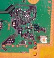
COK-002 SC UART testpads
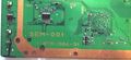
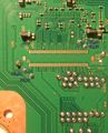
SEM-001 SC UART testpads
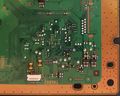
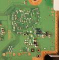
DIA-001 SC UART testpads
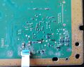
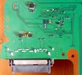
DIA-002 SC UART testpads
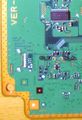
VER-001 SC UART testpads
DYN-001 SC UART testpads
SUR-001 SC and SB UART testpads
JTP-001 SC and SB UART testpads
JSD-001 SC and SB UART testpads
KTE-001 SC and SB UART testpads
SW3 SC UART testpads


You can attach a 3.3v TTL cable (LV-TTL) to the UART on syscon (UART0_TxD, UART0_RxD). Baud rate is 57600. There is a simple plaintext protocol involved. This varies on different syscon models. Example:
<command>:<hash>
Where the hash is the sum of command bytes & 0xFF.
You should terminate commands with \r\n, the syscon messages are only terminated with \n.
Samples
Here are some of the commands/messages encountered:
Messages:
Power applied (standby mode)
OK 00000000:3A

Power on
# (PowerOn State):7F

Power off (Hard shutdown)
# (PowerOff State):DD

After Fan test:
# (PowerOff State) (Fatal):36

No text, invalid hash:
NG F0000002:4D
Commands:
VER:ED
OK 00000000 S1E 00 00 065D:A4
OK 00000000 S1E 01 0B 00 0832:A3 (on DYN-001 board)
OK 00000000 S1E 02 03 00 0918:9A (on KTE-001 board)

ERRLOG:CB
OK 00000000:3A

DATE:1E
NG F0000003:4E

C:F1:BUZ
E:4F:NG F0000004
E:50:NG F0000005 (in DIAG mode)

C:D0:CID
E:50:NG F0000005

C:D0:CID GET
E:50:NG F0000005

C:DA:EEP
E:50:NG F0000005

C:DA:EEP GET
E:50:NG F0000005

C:E6:EEP SET
E:50:NG F0000005

C:D5:FAN
E:50:NG F0000005

C:83:FAN START
E:50:NG F0000005

C:3B:FAN STOP
E:50:NG F0000005

C:F4:KSV
E:50:NG F0000005

C:ED:REV
E:50:NG F0000005

C:F8:SPU
E:50:NG F0000005

C:FD:AUTH1
0000802000000000003000309C0EDB3F
E603EDB98A38DDC09400A2AB2DDE8CAB
0AECFE951FF7E2E8D8A7CF2202719F81
2F36DE83B424C27063C274CB0000E46B
<Important Note: 0x40 bytes>

E:5D:NG E00000C0

C:34:BOOT
E:50:NG F0000005
See also Syscon commands.
Bruteforcing commands: http://pastebin.com/CNei0xbC
VERY IMPORTANT:
- Max size of a command is 11 characters, 16 if you count with C:<hash>:
- Sending a command with 11 chars results in NO OUTPUT
- Sending a command with more than 11 chars results in NG F0000002
- Max size of a command on DECR is 135, 140 if you count with C:<hash>:
Syscon EEPROM (SPI)
| BGA | Name | Description |
|---|---|---|
| F16 | CSB | Chip Select (needs to be low) |
| H16 | DO | Serial Data Output |
| G16 | DI | Serial Data Input |
| E16 | SKB | Serial Data Clock |
| J15 | WCB | Write Protect |
| J16 | RBB | Ready/Busy |
| G11 | VDDep | + 3.3V |
| C15 | VSSep | GND |
Syscon JTAG
It is disabled in factory after production on retail models.
| BGA | Name | Description |
|---|---|---|
| L8 | JRTCK | Return Test Clock |
| K8 | JTCK | Test Clock |
| K9 | JTDO | Test Data Out |
| L9 | JTMS | Test Mode State / Test Mode Select |
| K7 | JTDI | Test Data In |
| L7 | JNTRST | Test Reset |
Syscon underlying ports
Syscon BE SPI Bus
| BGA | Name | Description |
|---|---|---|
| M2 | BE_SPI_CS | Chip Select |
| N2 | BE_SPI_DO | Serial Data Output |
| M1 | BE_SPI_DI | Serial Data Input |
| N1 | BE_SPI_CLK | Serial Data Clock |
| P2 | BE_RESET | CellBE Reset |
| P1 | BE_POWGOOD | CellBE PowerGood |
| T2 | BE_INT | CellBE Interrupt |
Syscon RSX SPI Bus
| BGA | Name | Description |
|---|---|---|
| E2 | RSX_SPI_CS | Chip Select |
| F2 | RSX_SPI_DO | Serial Data Output |
| F1 | RSX_SPI_DI | Serial Data Input |
| G1 | RSX_SPI_CLK | Serial Data Clock |
| G2 | RSX_RESET | RSX Reset |
| J2 | RSX_INT | RSX Interrupt |
Syscon SB SPI Bus
| BGA | Name | Description |
|---|---|---|
| B9 | SB_SPI_CS | Chip Select |
| B8 | SB_SPI_DO | Serial Data Output |
| A9 | SB_SPI_DI | Serial Data Input |
| A8 | SB_SPI_CLK | Serial Data Clock |
| D11 | SB_RESET | SB Reset |
| D9 | SB_INT | SB Interrupt |
Testpads and alternative solder points
- The identification of the syscon UART testpads can be made by grouping the motherboard models in a similar way we was doing with the layouts of the hardware flashers, there are 7 retail testpads layouts:
- Layout 1 = COK-001, COK-002 (fat, mullion, NAND)
- Layout 2 = SEM-001 (fat, mullion, NAND)
- Layout 3 = DIA-001, DIA-002 (fat, mullion, NOR)
- Layout 4 = VER-001 (fat, sherwood, NOR)
- Layout 5 = DYN-001 (slim, sherwood, NOR)
- Layout 6 = SUR-001, JTP-001, JSD-001, KTE-001 (slim, sherwood, NOR)
- Layout 7 = MSX-001, MPX-001, NPX-001, PPX-001, PQX-001, RTX-001, REX-001 (superslim, sherwood, NOR/eMMC)
DIA-001 and DIA-002
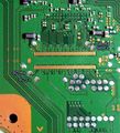
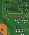
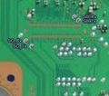
This points are availables to intercept signals by soldering wires, attaching probes, osciloscopes, etc... The photos are only orientatives to follow the traces, there's no need to remove the SYSCON to intercept this signals so can be done while its working
All this points has been hardware reverse engineered from a CECHH02/DIA-001 motherboard
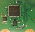
Topside Pinout

| Pin # | Name | Description |
|---|---|---|
| B3 | SW_10 | Unknown |
| A6 | MC_RESERVED2 | Unknown |
| E10 | MUL_CHKSTP_OUT | Unknown |
| C15 | VSS | Power Ground |
| B16 | OSCOUT | Goes to unpopulated crystal |
| C16 | OSCIN | From unpupulated crystal |
| B15 | POW_FAIL | Power Failure Signal |
| H1 | PN5 | Unknown |
| H2 | PN6 | Unknown |
| R1 | PM7 | Unknown |
| R2 | PM6 | Unknown |
| M4 | SW9 | Unknown |
| M10 | XDR_FET_SCK | Unknown |
Bottomside Pinout


| Pin # | Name | Description |
|---|---|---|
| R5 | VDD | +3.3v |
| R7 | DVDD | +1.8v |
| C15 | VSS | Power Ground |
| N16 | DIAG_MODE | Unknown |
| N15 | BACKUP_MODE | Unknown |
| P16 | UART0_TxD | Serial |
| P15 | UART0_RxD | Serial |
| R9 | PQ1 | Unknown |
| B12 | POW_SW | Power Switch |
| A12 | EJECT_SW | Eject Switch |
| L7 | JNTAST | JTAG |
| L8 | JRTCK | JTAG |
| L9 | JTMS | JTAG |
| K7 | JTDI | JTAG |
| K8 | JTCK | JTAG |
| K9 | JTDO | JTAG |
| M6 | SW_7_B | Unknown |
| M8 | FANPWM1 | Unknown |
| E5 | GX_VSRT | Unknown |
| B5 | DVE_RST | Unknown |
| G4 | HDMI_RST1 | Unknown |
| D4 | XDR_FET_RST | Unknown |
| |||||||||||||||||||||||||||||||||||||||||||||||||||||||||||||||||||||||||||||||||||||||||||||||||||||||||||||||||||||||||||||||||||||||||||||||||||||||||||||||||||||||||||||
