DSW-001: Difference between revisions
Jump to navigation
Jump to search
mNo edit summary |
mNo edit summary |
||
| (One intermediate revision by the same user not shown) | |||
| Line 1: | Line 1: | ||
= Description = | = Description = | ||
*Part number: 1-880-056-11 | *Part number: 1-880-056-11 | ||
* | *[[DSW-001]] is a [[Switch boards|switch board]] compatible with PS3 models: | ||
** [[CECH-20xx]] with [[DYN-001]] motherboard | **[[CECH-20xx]] with [[DYN-001]] motherboard | ||
*Notes: | *Notes: | ||
| Line 22: | Line 22: | ||
= Modding = | = Modding = | ||
Enabling contour LEDs in DSW-001 Switch board: [http://ps3gunz.org/forum/viewtopic.php?pid=590435 Original (french)] [http://translate.google.com/translate?sl=fr&tl=en&js=n&prev=_t&hl=es&ie=UTF-8&u=http%3A%2F%2Fps3gunz.org%2Fforum%2Fviewtopic.php%3Fpid%3D590435&act=url Google translated (english)] | |||
{{Console Components}}<noinclude>[[Category:Main]]</noinclude> | {{Console Components}}<noinclude>[[Category:Main]]</noinclude> | ||
Latest revision as of 03:56, 20 July 2017
Description[edit | edit source]
- Part number: 1-880-056-11
- DSW-001 is a switch board compatible with PS3 models:
- Notes:
- Contour leds - the leds are hidden close to the usb port under the main touch panel. none of the hidden Leds are grounded out but, always receives V+ even when in standby ( red light standby ) reason is unknown and has been found even back on first gen models.
- Compatibility with other ps3 models - this board will work with out back white, hidden, eject led, and 10th gnd pin on a 300X model full power eject and red and green led, A KSW-001 Will not work on a 200X model (dsw-001 slot).
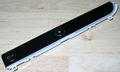
Switch board DSW-001 (top view)
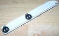
Switch board DSW-001 (bottom view)
Switch board DSW-001 (PCB top view)
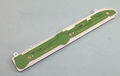
Switch board DSW-001 (PCB bottom view)
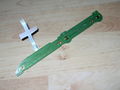
DSW-001 image diagram (reverse numbering)
.jpg)
.jpg)
.jpg)
.jpg)

Pinout[edit | edit source]
| Pin | Name | Connected to | Description | |
|---|---|---|---|---|
| On Motherboard | On Switch board | |||
| 1 | RMC_IN ? | Syscon SW2-30x, pin 13 | Testpad | Only This line have a Testpad @ switchboard, seems that it is a service pin. Also connected to a pin of a Service Connectors ? |
| 2 | SW_PWM ? | Syscon SW2-30x, pin 12 | 4x CONTOUR LEDs | Permanently inactive by default. On Switch board is connected to a transistor driving 3 LEDs: TWO BLUE AND ONE RED. |
| 3 | ? | Syscon SW2-30x, pin 11 | 2x White leds - | Inner LEDs for EJECT button backlight |
| 2x White leds - | Inner LEDs for POWER button backlight | |||
| 4 | POW_SW | Syscon SW2-30x, pin 110 | Power switch |
Sink to ground to activate. |
| 5 | EJECT_SW | Syscon SW2-30x, pin 111 | Eject switch |
Sink to ground to activate. |
| 6 | POW_LED | Syscon SW2-30x, pin 5 | Green led | Connects to bottom-left corner pin (green gnd) of dual red/green LED over power switch. |
| 7 | STBY_LED | Syscon SW2-30x, pin 6 | Red led | Connects to top-left corner pin (red gnd) of dual red/green LED over power switch. |
| 8 | BD_LED | BluRay Connector, pin 13 | Blue led | Connects to blue LED over eject switch. |
| 9 | GND | GND | GND | Ground |
| 10 | +5V_EVER | Power Supply Connector (CN101), pin 1 | VCC | 5V Standby |
- above top panel view port behind pcb. resistors was not tested.
How it works[edit | edit source]
Modding[edit | edit source]
Enabling contour LEDs in DSW-001 Switch board: Original (french) Google translated (english)
| ||||||||||||||||||||||||||||||||||||||||||||||||||||||||||||||||||||||||||||||||||||||||||||||||||||||||||||||||||||||||||||||||||||
