Talk:E3
This page needs clean up and sections ready for release moved to main page.
E3 Flasher Switches Explained
switch 1. only works if the NOR Tristate wire has been soldered, this is used for brick recovery. up = on / down = off and must be selected while the console is off.
switch 2. is used for dual booting and only works if the dual boot wire has been soldered to SBCE. up = e3 nor chip / down = ps3 nor chip.
switch 3. sets the e3 flasher into read or write mode. up = read from selected nor chip / down = write to selected nor chip.
switch 4. selects whether read from the microSD card or nor chip on the PS3. up = read from ps3 nor chip / down = read from microSD card.
switch 5. used to select which chip the flasher should read or write to. up = chip onboard the e3 flasher / down = chip on ps3.
switch 6. is lock or unlock? i have no idea what this actually does. i just leave it in the down position. which seems to work!
| FLASH FUN PS3 MODE |
CFW OFW |
BACKUP PROGRAM |
OB FLASH MICRO SD |
OB FLASH PS3 FLASH |
UNLOCK LOCK |
EXPLANATION |
|---|---|---|---|---|---|---|
| DOWN | DOWN | UP | DOWN | DOWN | DOWN | When start is pressed data stored on the ps3 nor chip will be copied to the microSD card. a file called bkpps3.bin will be created, or three files bkpps30.bin, bkpps31.bin, bkpps32.bin if you have a latest update from e3 |
| DOWN | DOWN | UP | DOWN | UP | DOWN | When start is pressed data stored on the e3 nor chip will be copied to the microSD card. a file called bkpe3.bin will be created. |
| DOWN | DOWN | DOWN | DOWN | DOWN | DOWN | Write data stored on the microSD card to the ps3 nor chip, a file named bkpe3.bin must be present. |
| DOWN | DOWN | DOWN | DOWN | UP | DOWN | Write data stored on the microSD card to the 33 nor chip, a file named bkpps3.bin must be present. make sure you have a good backup before writing. |
| DOWN | DOWN | DOWN | DOWN | UP | DOWN | Write data stored on the microSD card to the e3 nor chip, a file named bkpe3.bin must be present. |
| UP | DOWN | DOWN | DOWN | DOWN | DOWN | e3 recovery mode, if console is bricked! nor tristate wire must be soldered. a file named bkpps3.bin must be on the microSD card. |
| UP | DOWN | DOWN | UP | DOWN | DOWN | e3 recovery mode, if console is bricked. nor tristate wire soldered and you have dual boot options this setting will duplicate data from the e3 nor chip to the ps3 nor chip. |
| DOWN | UP | DOWN | DOWN | DOWN | DOWN | Used for dual booting, dual boot wire must be soldered. when up is selected the console will boot using data stored on the e3 nor chip. if down is selected the console will boot using data stored on the ps3 nor chip |
| DOWN | DOWN | UP | UP | UP | UP | Used to update the e3 flasher, update.bin must be stored on the microSD card |
TechnoDon working on wiki.. do not delete!
n00b GUIDE: Downgrade from 3.56 - 4.21 OFW to 3.55 OFW w/ E3 Flasher via Rogero v3.2 / v3.3
NOTE: This is NOT my tutorial. It is a compiled version of various articles written in PS3DEVWIKI.
With special guidance from domelec and eussNL. Thank you for your patience.
All credits goes to PS3DEVWIKI, domelec, eussNL and #ps3downgrade community. And also Rogero for his awesome CFW.
E3 Hardware Installation video w eng subs
Once hardware installation is done check that E3 Flasher LIGHTS UP when PS3 is turned on. Then turn it off.
During any of the below processes, should BLUE LED not light up as stated, read E3 Error Codes
How to update E3 Flasher
1. Insert blank microSD via any microSD card reader into PC.
2. Download update.bin (Samsung update Multi consoles) and put in the root directory of microSD
3. Check E3 Flasher: Make sure switches 1 & 2 should be down, switch 3, 4, 5, 6 should be in the up position.
4. Power PS3 "ON", the process will begin automatically
5. When all 8 LEDS light up, update is successful.
How to make NOR Backup
1. Insert the blank micro SD card into the e3 flasher 2. Check E3 Flasher: Make sure switches 1 & 2 is down, switch 3 should be in the up position, switches 4, 5 & 6 should also be down. 3. Turn PS3 on, wait till it loads to XMB (Main Menu). 4. Press START (Upper red button) on E3 Flasher to begin the process. 5. Wait till all 8 BLUE LEDs light up from left to right. 6. Once completed BLUE LEDs will flash, alternating between 4 a time.
Checking the NOR backups for errors
1. Remove the micro SD card from the E3 Flasher and insert into your PC.
2. If update is done correctly, you will see three backups on the microSD card (bkpps30.bin, bkpps31.bin & bkpps32.bin and the e3flasher text log file) or (bkpps3.bin and log file)
3. Use Flowrebuilder4.2.2.0 to Bytereverse anyone of the files. (Operation "Byte reverse and EXTRACT a NOR dump file")
4. Follow Validating Flash Dumps
OR
Upload it to mediafire and paste link at #ps3downgrade channel.
Be POLITE and PATIENT, someone will assist you.
Manual E3 downgrade
1. Download E3%20downgrade.rar and extract contents
2. Using autopatcher from Flowrebuilder4.2.2.0
3. Select "PATCH a Byte reversed NOR dump or an interleaved and unscrambled NAND dump."
4. Select as Input Dump File: the unmodified dump -> bkpps30.bin,bkpps32.bin,bkpps32.bin or bkpps3.bin (AC 0F FF E0 / AD DE EF BE)
5. Select as Patch file: progskeet_patch.txt
6. You will a see bkpps31.patch.bin created in the same folder as the input dump file
7. Rename it to bkpps31.bin and copy it over to your microSD card
Flashing the Patched file
1. Insert the microSD card into the E3 Flasher.
2. Check E3 Flasher: Switches 1, 2, 3, 4, 5 should be down and Switch 6 (lock/unlock) should be in the up position.
3. Turn on PS3 and wait for XMB to load.
4. Press START on the E3 flasher and the flashing will begin.
5. You will see the BLUE LEDS light up one by one. (once finished the lights will flash alternatively)
Entering FSM
Download lv2diag.self files
and Rogero CFW V3.2 (spoof 4.20) or Rogero CFW V3.4 (spoof 4.21)
1. Insert the FSM dongle into RIGHT usb port on PS3
2. Press POWER ON then press EJECT as fast as possible.
3. PS3 should turn on and then off automatically.
4. Using a FAT32 Formatted USB, put Rogero CFW v3.2 and lv2diag.self (Enter, File 1) onto root of USB drive.
5. Turn PS3 on, there should be no visual, let Rogero CFW install. (approx 10mins)
6. PS3 will automatically off.
7. Take USB stick out, check for Log if process was a success.
8. Again if unsure, ask for help at #ps3downgrade. Be POLITE and PATIENT
9. Once sure that the process went off correctly, turn on PS3
10. PS3 should boot into XMB, look for RED box with Factory/Service Mode written.
11. You are in FSM.
Exiting FSM
1. Put lv2diag.self (Exit, File 2) onto root of USB drive and remove lv2diag.self (Enter, File 1)
2. Turn PS3 on.
3. It will turn straight back off.
4. Take out USB, delete lv2diag.self. Create folders PS3\UPDATE\ put PS3UPDAT.pup (Rogero) into it
Installing Rogero via Recovery
Boot into recovery mode
1. With the system in standby mode (RED LIGHT) . Press and hold the power button down until the system turns on and then off again. Release the power button.
2. After about 1 - 2 seconds press and hold the power button again, until you hear 2 consecutive beeps. Release the power button. During this step you will actually here three beeps. There will be one single beep then a short delay followed by the 2 consecutive beeps. Only release the the power button after the 2 consecutive beeps.
3. You will then be instructed to plug in a controller, via the usb cord, and press the PS button : "Connect the controller using a USB cable and then press the PS button".
4. At this point the PS3 Recovery Menu will be shown on the screen.
5. Select menu option 6 : 6. System Update
6. Plug USB in, follow on screen instructions.
QA Toggle
1. Download QA Toggle
2. Place into root of USB.
3. Plug into PS3
4. Boot PS3 into XMB, install QA Toggle via XMB
5. Run QA Toggle, you will hear 2 beeps if successful, this means QA Flagged.
6. Turn off PS3
Installing OFW 3.55
Download OFW 3.55
1. Put PS3UPDAT.pup (OFW 3.55) into PS3\UPDATE\ and replace the Rogero pup
2. Boot into recovery mode (same as above)
3. Choose option 6. System Update.
4. Plug USB in, follow on screen instructions.
5. You are downgraded and dehashed now.
Installing CFW
1. Put PS3UPDAT.pup (Rogero CFW) into PS3\UPDATE\ and replace the OFW 3.55 pup
2. From XMB, run System Update > Choose from storage media.
3. Now you are on Rogero CFW.
Written by lyradblac.
If this guide proves useful and you do make money through it, please donate to PS3DEVWIKI.
This guide belongs to PS3DEVWIKI, any permissions to copy should be asked from them.
http://www.ps3hax.net/showthread.php?p=310228#post310228 http://www.ps3hax.net/showthread.php?t=30815
http://imageshack.us/f/221/coverboardfronts.jpg/
Front of E3:
- microSD slot
- Start button
- Stop button
- LED: flash fun?
- LED:PS1 mode
- Switch?
- LED: CFW
- LED: OFW
- Switch?
- LED: Backup
- LED: Prog
- Switch?
- marking: Backup
- LED: OB Flash
- MicroSD
- Switch?
- LED: ON Flash
- LED: PS3Flash
- Switch?
- marking: Prog
- LED: Unlock
- LED: Lock
- ESATA Plug
- microUSB Plug
See it all here: http://www.youtube.com/watch?v=-FJsuc_uAjc
ps3hax_E3 FLASHER installation manual.pdf (3.12 MB)
Maximum harddrive 2.5TB according to E3 website (currently down)
   Dual Boot 3.7OFW and 3.55CFW on same PS3
   Downgrade 3.7 to 3.55 in 5min
   16M NOR FLASH ON board
   3 save MODE, can save data in TF, NOR FLASH on board and PC HD
   1 KEY operation, simple is best
   Upgradable from TF card or PC USB
   Compatiable all device like PS3/WII/XBOX360/MP3/DVD/BD/MP4/Table PC which has NAND or NOR flash memory.
   Integrated lots of interface, perfectly extension, will have more function with future new E3 accessory.
   E3 flasher Limited version includes 8 accessory, suggested retail price $88 USD, total production run only 3000 units!
New E3 PS3 Slim NOR clip : http://oi52.tinypic.com/dh8p4z.jpg
E3 still uses 4 solderpads : BVCC, VCC, SBE, SBCE http://imgur.com/a/dHVb1#clgBM
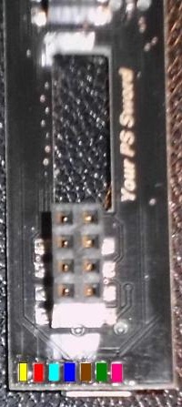
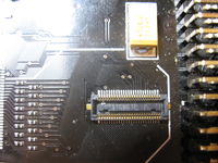
connector on subboard for the clip
P4 / Panasonic - Narrow Pitch (Board to Board) Connectors
need the Retention Fitting Socket
untested, let us know if it works
Shops:
- http://parts.digikey.com/1/parts/1627663-conn-socket-p4-4mm-50pos-smd-axk750147g.html
- http://excellence-china.en.alibaba.com/product/409636072-211994488/AXK750147G.html
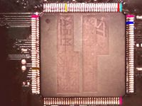
STMicroelectronics ARM used for the e3 board
 JTG pin (with JTAG? (if so, then the pins would be 'GND, TRST, 3,3V, TDO, TMS, TDI, TCK. see also Injectus pinout) |


