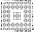
CXD9963GB: Difference between revisions
Jump to navigation
Jump to search
No edit summary |
No edit summary |
||
| (2 intermediate revisions by one other user not shown) | |||
| Line 7: | Line 7: | ||
**[[CECH-25xx]] with motherboard [[JTP-001]] or [[JSD-001]] | **[[CECH-25xx]] with motherboard [[JTP-001]] or [[JSD-001]] | ||
**[[CECH-30xx]] with motherboard [[KTE-001]] | **[[CECH-30xx]] with motherboard [[KTE-001]] | ||
**[[CECH-40xx]] with motherboard [[MSX-001]] | **[[CECH-40xx]] with motherboard [[MSX-001]], [[MPX-001]] or [[NPX-001]] | ||
**[[CECH-43xx]] with motherboard [[REX-001]] | **[[CECH-42xx]] with motherboard [[NPX-001]], [[PPX-001]] or [[PQX-001]] | ||
**[[CECH-43xx]] with motherboard [[REX-001]] or [[RTX-001]] | |||
As these [[Motherboard Revisions | motherboards]] do not have an [[USB]] hub chip, the two frontports are directly connected to this [[South Bridge]] | As these [[Motherboard Revisions | motherboards]] do not have an [[USB]] hub chip, the two frontports are directly connected to this [[South Bridge]] | ||
| Line 26: | Line 27: | ||
{| class="wikitable mw-datatable sortable" style="width:100%; line-height:1em; font-size:0.9em" | {| class="wikitable mw-datatable sortable" style="width:100%; line-height:1em; font-size:0.9em" | ||
|+CXD9963GB pad layout | |+<div style="margin-bottom:2px">CXD9963GB pad layout</div> | ||
! Pad !! colspan="2" | Name !! style="padding:1px" | Type !! Description | ! Pad !! colspan="2" | Name !! style="padding:1px" | Type !! Description | ||
|- | |- | ||
| Line 37: | Line 38: | ||
| data-sort-value="0A03" | A3 || || || || | | data-sort-value="0A03" | A3 || || || || | ||
|- | |- | ||
| data-sort-value="0A04" | A4 || WIFI_DATA_1 | | data-sort-value="0A04" | A4 || <abbr title="This name is a custom madeup, not official">WIFI_DATA_1</abbr> || ? || ? || Connected to wifi/BT module. See: [[Media:KTE-001_wifitraces.jpg|wifi/BT 10x7 pinout]] or [[Media:REX-001_wifitraces.jpg|wifi/BT 9x7 pinout]] | ||
|- | |- | ||
| data-sort-value="0A05" | A5 || || || || | | data-sort-value="0A05" | A5 || || || || | ||
| Line 83: | Line 84: | ||
| data-sort-value="0B03" | B3 || || || || | | data-sort-value="0B03" | B3 || || || || | ||
|- | |- | ||
| data-sort-value="0B04" | B4 || WIFI_DATA_2 | | data-sort-value="0B04" | B4 || <abbr title="This name is a custom madeup, not official">WIFI_DATA_2</abbr> || ? || ? || Connected to wifi/BT module. See: [[Media:KTE-001_wifitraces.jpg|wifi/BT 10x7 pinout]] or [[Media:REX-001_wifitraces.jpg|wifi/BT 9x7 pinout]] | ||
|- | |- | ||
| data-sort-value="0B05" | B5 || || || || | | data-sort-value="0B05" | B5 || || || || | ||
| Line 261: | Line 262: | ||
| data-sort-value="0E99" style="padding:0px" | || colspan="4" data-sort-value="ZZZ" style="padding:0px" | | | data-sort-value="0E99" style="padding:0px" | || colspan="4" data-sort-value="ZZZ" style="padding:0px" | | ||
|- | |- | ||
| data-sort-value="0F01" | F1 || WIFI_CTRL | | data-sort-value="0F01" | F1 || <abbr title="This name is a custom madeup, not official">WIFI_CTRL</abbr> || ? || ? || Connected to wifi/BT module. See: [[Media:KTE-001_wifitraces.jpg|wifi/BT 10x7 pinout]] or [[Media:REX-001_wifitraces.jpg|wifi/BT 9x7 pinout]] | ||
|- | |- | ||
| data-sort-value="0F02" | F2 || || || || | | data-sort-value="0F02" | F2 || || || || | ||
Latest revision as of 22:24, 14 August 2024
CXD9963GB[edit | edit source]
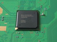
- Used on PS3 models:
- CECH-20xx with motherboard DYN-001
- CECH-21xx with motherboard SUR-001
- CECH-25xx with motherboard JTP-001 or JSD-001
- CECH-30xx with motherboard KTE-001
- CECH-40xx with motherboard MSX-001, MPX-001 or NPX-001
- CECH-42xx with motherboard NPX-001, PPX-001 or PQX-001
- CECH-43xx with motherboard REX-001 or RTX-001
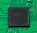
As these motherboards do not have an USB hub chip, the two frontports are directly connected to this South Bridge
Gallery[edit | edit source]
Pinout[edit | edit source]
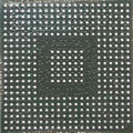
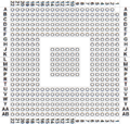
| Pad | Name | Type | Description | |
|---|---|---|---|---|
| Internal | External | |||
| A1 | N/A | N/A | N/A | Missing pad |
| A2 | ||||
| A3 | ||||
| A4 | WIFI_DATA_1 | ? | ? | Connected to wifi/BT module. See: wifi/BT 10x7 pinout or wifi/BT 9x7 pinout |
| A5 | ||||
| A6 | ||||
| A7 | GND | GND | Ground | |
| A8 | ||||
| A9 | ||||
| A10 | ||||
| A11 | ||||
| A12 | ||||
| A13 | ||||
| A14 | ||||
| A15 | ||||
| A16 | ||||
| A17 | ||||
| A18 | ||||
| A19 | ||||
| A20 | ||||
| A21 | ||||
| A22 | ||||
| B1 | ||||
| B2 | ||||
| B3 | ||||
| B4 | WIFI_DATA_2 | ? | ? | Connected to wifi/BT module. See: wifi/BT 10x7 pinout or wifi/BT 9x7 pinout |
| B5 | ||||
| B6 | ||||
| B7 | ||||
| B8 | ||||
| B9 | ||||
| B10 | ||||
| B11 | ||||
| B12 | ||||
| B13 | ||||
| B14 | ||||
| B15 | ||||
| B16 | ||||
| B17 | ||||
| B18 | ||||
| B19 | ||||
| B20 | ||||
| B21 | ||||
| B22 | ||||
| C1 | ||||
| C2 | ||||
| C3 | ||||
| C4 | ||||
| C5 | ||||
| C6 | ||||
| C7 | ||||
| C8 | ||||
| C9 | ||||
| C10 | ||||
| C11 | ||||
| C12 | ||||
| C13 | ||||
| C14 | ||||
| C15 | ||||
| C16 | ||||
| C17 | ||||
| C18 | ||||
| C19 | ||||
| C20 | ||||
| C21 | ||||
| C22 | ||||
| D1 | ||||
| D2 | ||||
| D3 | ||||
| D4 | ||||
| D5 | ||||
| D6 | ||||
| D7 | ||||
| D8 | ||||
| D9 | ||||
| D10 | ||||
| D11 | ||||
| D12 | ||||
| D13 | ||||
| D14 | ||||
| D15 | ||||
| D16 | ||||
| D17 | ||||
| D18 | ||||
| D19 | ||||
| D20 | ||||
| D21 | ||||
| D22 | ||||
| E1 | ||||
| E2 | ||||
| E3 | ||||
| E4 | ||||
| E5 | ||||
| E6 | ||||
| E7 | ||||
| E8 | ||||
| E9 | ||||
| E10 | ||||
| E11 | ||||
| E12 | ||||
| E13 | ||||
| E14 | ||||
| E15 | ||||
| E16 | ||||
| E17 | ||||
| E18 | ||||
| E19 | ||||
| E20 | ||||
| E21 | ||||
| E22 | ||||
| F1 | WIFI_CTRL | ? | ? | Connected to wifi/BT module. See: wifi/BT 10x7 pinout or wifi/BT 9x7 pinout |
| F2 | ||||
| F3 | ||||
| F4 | ||||
| F5 | ||||
| F6 | ||||
| F7 | ||||
| F8 | ||||
| F9 | ||||
| F10 | ||||
| F11 | ||||
| F12 | ||||
| F13 | ||||
| F14 | ||||
| F15 | ||||
| F16 | ||||
| F17 | ||||
| F18 | ||||
| F19 | ||||
| F20 | ||||
| F21 | ||||
| F22 | ||||
| G1 | ||||
| G2 | ||||
| G3 | ||||
| G4 | ||||
| G5 | ||||
| G6 | ||||
| G7 | N/A | N/A | N/A | Missing pad |
| G8 | N/A | N/A | N/A | Missing pad |
| G9 | N/A | N/A | N/A | Missing pad |
| G10 | N/A | N/A | N/A | Missing pad |
| G11 | N/A | N/A | N/A | Missing pad |
| G12 | N/A | N/A | N/A | Missing pad |
| G13 | N/A | N/A | N/A | Missing pad |
| G14 | N/A | N/A | N/A | Missing pad |
| G15 | N/A | N/A | N/A | Missing pad |
| G16 | N/A | N/A | N/A | Missing pad |
| G17 | ||||
| G18 | ||||
| G19 | ||||
| G20 | ||||
| G21 | ||||
| G22 | ||||
| H1 | ||||
| H2 | ||||
| H3 | ||||
| H4 | ||||
| H5 | ||||
| H6 | ||||
| H7 | N/A | N/A | N/A | Missing pad |
| H8 | N/A | N/A | N/A | Missing pad |
| H9 | N/A | N/A | N/A | Missing pad |
| H10 | N/A | N/A | N/A | Missing pad |
| H11 | N/A | N/A | N/A | Missing pad |
| H12 | N/A | N/A | N/A | Missing pad |
| H13 | N/A | N/A | N/A | Missing pad |
| H14 | N/A | N/A | N/A | Missing pad |
| H15 | N/A | N/A | N/A | Missing pad |
| H16 | N/A | N/A | N/A | Missing pad |
| H17 | ||||
| H18 | ||||
| H19 | ||||
| H20 | ||||
| H21 | ||||
| H22 | ||||
| J1 | ||||
| J2 | ||||
| J3 | ||||
| J4 | ||||
| J5 | ||||
| J6 | ||||
| J7 | N/A | N/A | N/A | Missing pad |
| J8 | N/A | N/A | N/A | Missing pad |
| J9 | ||||
| J10 | ||||
| J11 | ||||
| J12 | ||||
| J13 | ||||
| J14 | ||||
| J15 | N/A | N/A | N/A | Missing pad |
| J16 | N/A | N/A | N/A | Missing pad |
| J17 | ||||
| J18 | ||||
| J19 | ||||
| J20 | ||||
| J21 | ||||
| J22 | ||||
| K1 | ||||
| K2 | ||||
| K3 | ||||
| K4 | ||||
| K5 | ||||
| K6 | ||||
| K7 | N/A | N/A | N/A | Missing pad |
| K8 | N/A | N/A | N/A | Missing pad |
| K9 | ||||
| K10 | ||||
| K11 | ||||
| K12 | ||||
| K13 | ||||
| K14 | ||||
| K15 | N/A | N/A | N/A | Missing pad |
| K16 | N/A | N/A | N/A | Missing pad |
| K17 | ||||
| K18 | ||||
| K19 | ||||
| K20 | ||||
| K21 | ||||
| K22 | ||||
| L1 | ||||
| L2 | ||||
| L3 | ||||
| L4 | ||||
| L5 | ||||
| L6 | ||||
| L7 | N/A | N/A | N/A | Missing pad |
| L8 | N/A | N/A | N/A | Missing pad |
| L9 | ||||
| L10 | ||||
| L11 | ||||
| L12 | ||||
| L13 | ||||
| L14 | ||||
| L15 | N/A | N/A | N/A | Missing pad |
| L16 | N/A | N/A | N/A | Missing pad |
| L17 | ||||
| L18 | ||||
| L19 | ||||
| L20 | ||||
| L21 | ||||
| L22 | ||||
| M1 | ||||
| M2 | ||||
| M3 | ||||
| M4 | ||||
| M5 | ||||
| M6 | ||||
| M7 | N/A | N/A | N/A | Missing pad |
| M8 | N/A | N/A | N/A | Missing pad |
| M9 | ||||
| M10 | ||||
| M11 | ||||
| M12 | ||||
| M13 | ||||
| M14 | ||||
| M15 | N/A | N/A | N/A | Missing pad |
| M16 | N/A | N/A | N/A | Missing pad |
| M17 | ||||
| M18 | ||||
| M19 | ||||
| M20 | ||||
| M21 | ||||
| M22 | ||||
| N1 | ||||
| N2 | ||||
| N3 | ||||
| N4 | ||||
| N5 | ||||
| N6 | ||||
| N7 | N/A | N/A | N/A | Missing pad |
| N8 | N/A | N/A | N/A | Missing pad |
| N9 | ||||
| N10 | ||||
| N11 | ||||
| N12 | ||||
| N13 | ||||
| N14 | ||||
| N15 | N/A | N/A | N/A | Missing pad |
| N16 | N/A | N/A | N/A | Missing pad |
| N17 | ||||
| N18 | ||||
| N19 | ||||
| N20 | ||||
| N21 | ||||
| N22 | ||||
| P1 | ||||
| P2 | ||||
| P3 | ||||
| P4 | ||||
| P5 | ||||
| P6 | ||||
| P7 | N/A | N/A | N/A | Missing pad |
| P8 | N/A | N/A | N/A | Missing pad |
| P9 | ||||
| P10 | ||||
| P11 | ||||
| P12 | ||||
| P13 | ||||
| P14 | ||||
| P15 | N/A | N/A | N/A | Missing pad |
| P16 | N/A | N/A | N/A | Missing pad |
| P17 | ||||
| P18 | ||||
| P19 | ||||
| P20 | ||||
| P21 | ||||
| P22 | ||||
| R1 | ||||
| R2 | ||||
| R3 | ||||
| R4 | ||||
| R5 | ||||
| R6 | ||||
| R7 | N/A | N/A | N/A | Missing pad |
| R8 | N/A | N/A | N/A | Missing pad |
| R9 | N/A | N/A | N/A | Missing pad |
| R10 | N/A | N/A | N/A | Missing pad |
| R11 | N/A | N/A | N/A | Missing pad |
| R12 | N/A | N/A | N/A | Missing pad |
| R13 | N/A | N/A | N/A | Missing pad |
| R14 | N/A | N/A | N/A | Missing pad |
| R15 | N/A | N/A | N/A | Missing pad |
| R16 | N/A | N/A | N/A | Missing pad |
| R17 | ||||
| R18 | ||||
| R19 | ||||
| R20 | ||||
| R21 | ||||
| R22 | ||||
| T1 | ||||
| T2 | ||||
| T3 | ||||
| T4 | ||||
| T5 | ||||
| T6 | ||||
| T7 | N/A | N/A | N/A | Missing pad |
| T8 | N/A | N/A | N/A | Missing pad |
| T9 | N/A | N/A | N/A | Missing pad |
| T10 | N/A | N/A | N/A | Missing pad |
| T11 | N/A | N/A | N/A | Missing pad |
| T12 | N/A | N/A | N/A | Missing pad |
| T13 | N/A | N/A | N/A | Missing pad |
| T14 | N/A | N/A | N/A | Missing pad |
| T15 | N/A | N/A | N/A | Missing pad |
| T16 | N/A | N/A | N/A | Missing pad |
| T17 | ||||
| T18 | ||||
| T19 | ||||
| T20 | ||||
| T21 | ||||
| T22 | ||||
| U1 | ||||
| U2 | ||||
| U3 | ||||
| U4 | ||||
| U5 | ||||
| U6 | ||||
| U7 | ||||
| U8 | ||||
| U9 | ||||
| U10 | ||||
| U11 | ||||
| U12 | ||||
| U13 | ||||
| U14 | ||||
| U15 | ||||
| U16 | ||||
| U17 | ||||
| U18 | SB_SPI_CLK SYSCSSPICLK |
? | ? | Connected to Syscon pin 82 (LQFP 128 pins layout), or pin 61 (LQFP 100 pins layout) |
| U19 | SB_SPI_CS /SYSCSSPICS |
? | ? | Connected to Syscon pin 83 (LQFP 128 pins layout), or pin 35 (LQFP 100 pins layout) |
| U20 | ||||
| U21 | ||||
| U22 | ||||
| V1 | ||||
| V2 | ||||
| V3 | ||||
| V4 | ||||
| V5 | ||||
| V6 | ||||
| V7 | ||||
| V8 | ||||
| V9 | ||||
| V10 | ||||
| V11 | ||||
| V12 | ||||
| V13 | ||||
| V14 | ||||
| V15 | ||||
| V16 | ||||
| V17 | ||||
| V18 | ||||
| V19 | SB_SPI_DO SYSCSSPIDI |
? | ? | Connected to Syscon pin 80 (LQFP 128 pins layout), or pin 59 (LQFP 100 pins layout) |
| V20 | ||||
| V21 | ||||
| V22 | SYSCSSPIDO | ? | ? | Connected to Syscon pin 81 (LQFP 128 pins layout), or pin 60 (LQFP 100 pins layout) |
| W1 | ||||
| W2 | ||||
| W3 | ||||
| W4 | ||||
| W5 | ||||
| W6 | ||||
| W7 | ||||
| W8 | ||||
| W9 | ||||
| W10 | ||||
| W11 | ||||
| W12 | ||||
| W13 | ||||
| W14 | ||||
| W15 | ||||
| W16 | ||||
| W17 | ||||
| W18 | ||||
| W19 | ||||
| W20 | ||||
| W21 | ? | ? | ? | Connected to Syscon pin 46 (LQFP 128 pins layout), or pin 55 (LQFP 100 pins layout) |
| W22 | SB_INT SYSCSINT |
? | ? | Connected to Syscon pin 2 (LQFP 128 pins layout), or pin 3 (LQFP 100 pins layout) |
| Y1 | ||||
| Y2 | ||||
| Y3 | ||||
| Y4 | ||||
| Y5 | ||||
| Y6 | ||||
| Y7 | ||||
| Y8 | ||||
| Y9 | ||||
| Y10 | ||||
| Y11 | ||||
| Y12 | ||||
| Y13 | ||||
| Y14 | ||||
| Y15 | ||||
| Y16 | ||||
| Y17 | ||||
| Y18 | ||||
| Y19 | ||||
| Y20 | ||||
| Y21 | ||||
| Y22 | ||||
| AA1 | ||||
| AA2 | ||||
| AA3 | ||||
| AA4 | ||||
| AA5 | ||||
| AA6 | ||||
| AA7 | ||||
| AA8 | ||||
| AA9 | ||||
| AA10 | ||||
| AA11 | ||||
| AA12 | ||||
| AA13 | ||||
| AA14 | ||||
| AA15 | ||||
| AA16 | ||||
| AA17 | ? | ? | ? | Connected to Syscon pin 8 (LQFP 128 pins layout), or pin 2 (LQFP 100 pins layout) |
| AA18 | ? | ? | ? | Connected to Syscon pin 7 (LQFP 128 pins layout), or pin 10 (LQFP 100 pins layout) |
| AA19 | ||||
| AA20 | ||||
| AA21 | ||||
| AA22 | ||||
| AB1 | ||||
| AB2 | ||||
| AB3 | ||||
| AB4 | ||||
| AB5 | ||||
| AB6 | ||||
| AB7 | ||||
| AB8 | ||||
| AB9 | ||||
| AB10 | ||||
| AB11 | ||||
| AB12 | ||||
| AB13 | ||||
| AB14 | ||||
| AB15 | ||||
| AB16 | ||||
| AB17 | ||||
| AB18 | ||||
| AB19 | ||||
| AB20 | ||||
| AB21 | ||||
| AB22 | ||||
| |||||||||||||||||||||||||||||||||||||||||||||||||||||||||||||||||||||||||||||||||||||||||||||||||||||||||||||||||||||||||||||||||||||||||||||||||||||||||||||||||||||||||||||
