Test points/MechaCon UART: Difference between revisions
No edit summary |
No edit summary |
||
| (20 intermediate revisions by 4 users not shown) | |||
| Line 6: | Line 6: | ||
The publicly available service tools only support consoles up to the G-chassis (up to including SCPH-37000 and SCPH-39000 series).<br/> | The publicly available service tools only support consoles up to the G-chassis (up to including SCPH-37000 and SCPH-39000 series).<br/> | ||
PMAP additionally supports H and I chassis consoles (most SCPH-50000 series consoles). | PMAP additionally supports H and I chassis consoles (most SCPH-50000 series consoles). Support for other consoles is work in progress. | ||
Currently missing (please contribute): | Currently missing (please contribute): | ||
* GH-008, GH-016, GH-017, GH-018 | * GH-008, GH-016, GH-017, GH-018, GH-029, GH-036, GH-040 | ||
=Notes= | =How to connect= | ||
To enable the UART interface, the console must be put into testmode by pulling the TEST_MODE0 test point to ground. The interface operates at '''57600 baud 8N1''' (automatically set correctly by PMAP and the official service tools) and rather non-standard '''3.5 V'''. | |||
3.3 V signal levels work fine for communication, but care must be taken not to additionally connect an internal 3V3 voltage regulator, which is provided on some USB UART interfaces, to the console, since this will conflict with the console's own 3V5 voltage regulation and could damage the USB device and/or the console. On such interfaces, it should suffice to '''just connect Rx, Tx and GND'''. Even better would be to use a RS-232-to-TTL level shifter, which can take the 3V5 voltage as reference directly from the console itself. | |||
==Notes== | |||
*'''RX''' and '''TX''' are sometimes swapped in these pictures. This is due to the contributors not having unified their naming conventions, with some marking RX and TX as seen from the MechaCon's side and others marking RX and TX as seen from the PC's (or it's interface's) side. If you can't establish a connection one way, you should try swapping RX and TX and try again. There are plans for unifying the naming in the future. | *'''RX''' and '''TX''' are sometimes swapped in these pictures. This is due to the contributors not having unified their naming conventions, with some marking RX and TX as seen from the MechaCon's side and others marking RX and TX as seen from the PC's (or it's interface's) side. If you can't establish a connection one way, you should try swapping RX and TX and try again. There are plans for unifying the naming in the future. | ||
*The '''3.3V''' marked on most pictures are '''actually 3.5V''', since that's what MechaCon runs off. If you are using e.g. a RS232-to-TTL level shifter (like e.g. a MAX3232-based level shifter), the PS2's 3.5V need to be connected to your level shifter's Vcc. However, it should not be connected to anything that has it's own 3.3V regulator (like e.g. some USB-to-TTL converters), since the regulator on the PS2's board and your converter will end up in a feedback loop, potentially causing damage. There are plans for unifying the naming in the future. | *The '''3.3V''' marked on most pictures are '''actually 3.5V''', since that's what MechaCon runs off. If you are using e.g. a RS232-to-TTL level shifter (like e.g. a MAX3232-based level shifter), the PS2's 3.5V need to be connected to your level shifter's Vcc. However, it should not be connected to anything that has it's own 3.3V regulator (like e.g. some USB-to-TTL converters), since the regulator on the PS2's board and your converter will end up in a feedback loop, potentially causing damage. There are plans for unifying the naming in the future. | ||
| Line 76: | Line 81: | ||
===GH-026=== | ===GH-026=== | ||
[[File:GH-026 Mechacon UART.jpg|200px]] | |||
===GH-029=== | ===GH-029=== | ||
| Line 84: | Line 90: | ||
===GH-032=== | ===GH-032=== | ||
''Identical to GH-035''</br> | |||
[[File:GH-032 Mechacon UART.jpg|200px]] | |||
===GH-035=== | ===GH-035=== | ||
''Identical to GH-032''</br> | |||
[[File:GH-035 test points.png|200px]] | [[File:GH-035 test points.png|200px]] | ||
===GH-036=== | ===GH-036=== | ||
[[File:GH-036 UART Test Points.jpg|200px]] | |||
''Please contribute a good 3.5V test point'' | |||
===GH-037=== | ===GH-037=== | ||
| Line 98: | Line 109: | ||
===GH-041=== | ===GH-041=== | ||
[[File:GH-041.jpg|200px]] | |||
==GH-05X== | ==GH-05X== | ||
| Line 109: | Line 121: | ||
==GH-06X== | ==GH-06X== | ||
===GH-061=== | ===GH-061 (except GH-061-51)=== | ||
''On the top side, next to the Ethernet connector.''<br/> | |||
[[File:Slim79.png|200px]] | [[File:Slim79.png|200px]] | ||
''For GH-061-12, TX, RX, RMC, and Ground are the same as GH-061-22. 3.3 V/3.5 V point shown in that diagram might not supply enough amperage to power a USB-UART device requiring external power, so use an alternate 3.3v point such as the one recommended for installing Modbo.'' | |||
===GH-061-51=== | |||
''On the top side of the board, two points being above and one point being to the left of the MechaCon.''<br/> | |||
[[File:PS2 SLim GH-061-51 UART Points.jpg|200px]] | |||
===GH-062=== | ===GH-062=== | ||
''GH-062-02, located near the top left corner of the MechaCon.''<br/> | |||
[[File:GH-62-02 Solder Points for Test Mode.jpg|200px]] | |||
==GH-07X== | ==GH-07X== | ||
Latest revision as of 17:21, 4 November 2024
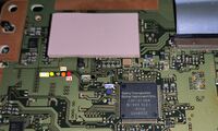
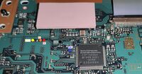
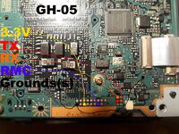
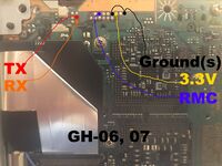
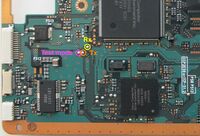
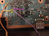
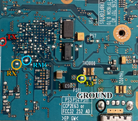
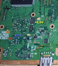
These are the test points exposing MechaCon's UART interface e.g. for CDVD Drive calibration using PMAP. These test points have also been used by Sony service centers via official service tools.
To put the console into service mode, the RMC/test mode test point needs to be grounded. This is necessary when recalibrating the drive and doing other stuff.
Depending on how you connect to the console, you might have to swap RX and TX with each other.
The publicly available service tools only support consoles up to the G-chassis (up to including SCPH-37000 and SCPH-39000 series).
PMAP additionally supports H and I chassis consoles (most SCPH-50000 series consoles). Support for other consoles is work in progress.
Currently missing (please contribute):
- GH-008, GH-016, GH-017, GH-018, GH-029, GH-036, GH-040
How to connect[edit | edit source]
To enable the UART interface, the console must be put into testmode by pulling the TEST_MODE0 test point to ground. The interface operates at 57600 baud 8N1 (automatically set correctly by PMAP and the official service tools) and rather non-standard 3.5 V.
3.3 V signal levels work fine for communication, but care must be taken not to additionally connect an internal 3V3 voltage regulator, which is provided on some USB UART interfaces, to the console, since this will conflict with the console's own 3V5 voltage regulation and could damage the USB device and/or the console. On such interfaces, it should suffice to just connect Rx, Tx and GND. Even better would be to use a RS-232-to-TTL level shifter, which can take the 3V5 voltage as reference directly from the console itself.
Notes[edit | edit source]
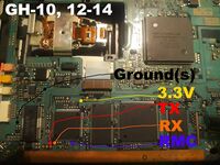
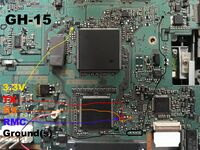
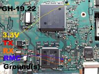
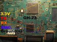
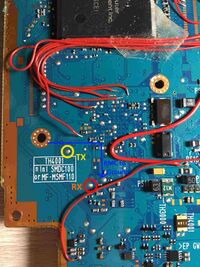
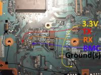
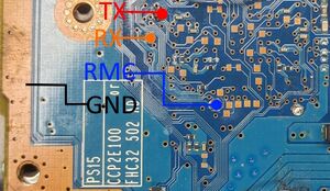
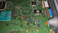
- RX and TX are sometimes swapped in these pictures. This is due to the contributors not having unified their naming conventions, with some marking RX and TX as seen from the MechaCon's side and others marking RX and TX as seen from the PC's (or it's interface's) side. If you can't establish a connection one way, you should try swapping RX and TX and try again. There are plans for unifying the naming in the future.
- The 3.3V marked on most pictures are actually 3.5V, since that's what MechaCon runs off. If you are using e.g. a RS232-to-TTL level shifter (like e.g. a MAX3232-based level shifter), the PS2's 3.5V need to be connected to your level shifter's Vcc. However, it should not be connected to anything that has it's own 3.3V regulator (like e.g. some USB-to-TTL converters), since the regulator on the PS2's board and your converter will end up in a feedback loop, potentially causing damage. There are plans for unifying the naming in the future.
- RMC is actually named TEST_MODE0. This mistake comes from the fact that the generic microcontroller that the SPC970-MechaCon is based on has an alternate function on the same pin called RMC (ReMoteController), which is an internal remote control signal decoder. This alternate function is unused on PS2 and does not exist on the Dragon-MechaCon. There are plans for unifying the naming in the future.
Playstation 2 Fat Motherboard Models[edit | edit source]
GH-00X[edit | edit source]
GH-001[edit | edit source]
GH-003[edit | edit source]
GH-004[edit | edit source]
Identical to GH-005
GH-005[edit | edit source]
GH-006[edit | edit source]
GH-007[edit | edit source]
Identical to GH-006
GH-008[edit | edit source]
GH-01X[edit | edit source]
GH-010[edit | edit source]
GH-012[edit | edit source]
Identical to GH-010
GH-013[edit | edit source]
Identical to GH-010
GH-014[edit | edit source]
Identical to GH-010
GH-015[edit | edit source]
GH-016[edit | edit source]
GH-017[edit | edit source]
GH-018[edit | edit source]
GH-019[edit | edit source]
GH-02X[edit | edit source]
GH-022[edit | edit source]
Identical to GH-019
GH-023[edit | edit source]
GH-026[edit | edit source]
GH-029[edit | edit source]
Playstation 2 Slim Motherboard Models[edit | edit source]
GH-03X[edit | edit source]
GH-032[edit | edit source]
GH-035[edit | edit source]
GH-036[edit | edit source]
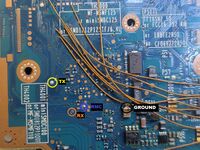 Please contribute a good 3.5V test point
GH-037[edit | edit source]
GH-04X[edit | edit source]
GH-040[edit | edit source]
GH-041[edit | edit source]
GH-05X[edit | edit source]
GH-051[edit | edit source]
GH-052[edit | edit source]
GH-06X[edit | edit source]
GH-061 (except GH-061-51)[edit | edit source]
On the top side, next to the Ethernet connector.
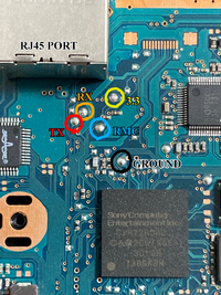
For GH-061-12, TX, RX, RMC, and Ground are the same as GH-061-22. 3.3 V/3.5 V point shown in that diagram might not supply enough amperage to power a USB-UART device requiring external power, so use an alternate 3.3v point such as the one recommended for installing Modbo.
GH-061-51[edit | edit source]
On the top side of the board, two points being above and one point being to the left of the MechaCon.

GH-062[edit | edit source]
GH-062-02, located near the top left corner of the MechaCon.

GH-07X[edit | edit source]
GH-070[edit | edit source]
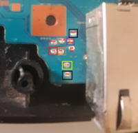
On the top side, next to the Ethernet connector
GH-071[edit | edit source]
Identical to GH-070
GH-072[edit | edit source]
Identical to GH-070
PSX Motherboard Models[edit | edit source]
XPD-001[edit | edit source]
Identical to XPD-005
