HSW-001
Description[edit | edit source]
- Part number: 1-881-946-11 (Unknown manufacturer), 1-881-946-21 (Produced by Foxconn)
- HSW-001 is a switch board compatible with PS3 models:
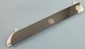
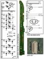
Switch board HSW-001 (top view)
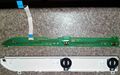
Switch board HSW-001 (PCB with ribbon cable, top view)
Switch board HSW-001, 1-881-946-11. Unknown manufacturer

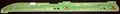
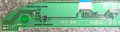
Switch board HSW-001 (PCB top view)
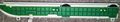
Switch board HSW-001 (PCB bottom view), 1-881-946-21. Produced by Foxconn
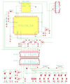
Switch board HSW-001 (JSD-001) schematic
Switch board HSW-001 (Contour LEDs subcircuit, unpopulated components)
PS3 Power control and switches schematic for CECH-25xx series
Motherboards JTP-001 or JSD-001, SYSCON SW-x series, Switch board HSW-001, and 4 pins PSU connector (CN101) for PSU models APS-270 or EADP-200DB
.jpg)
.jpg)
_schematic.jpg)

Pinout[edit | edit source]
| Pin | Name | Connected to | Description | |
|---|---|---|---|---|
| On Motherboard | On Switch board | |||
| 1 | SW_PWM ? | Syscon SW2-30x, pin 12 | 4x CONTOUR LEDs, transistor base pin | The transistor is located in the switch board and drives 2 LEDs with currentlimitor resistors of 3K Ω (red led at left-top) and 820 Ω (blue led at left-bottom) The circuit has unpopulated pads to add another transistor and another 2 LEDs for a total of 4 LEDs driven by a misterious syscon pin |
| 2 | +5V_EVER | Power Supply Connector (CN101), pin 1 | VCC | 5V Standby line from power supply connector CN101, the pin named 5V_EVER on motherboard and 5VSB on power supply |
| 3 | ? | Syscon SW2-30x, pin 11 | 2x White leds - | Inner LEDs for EJECT button backlight, with a currentlimitor resistor of 910 Ω |
| 2x White leds - | Inner LEDs for POWER button backlight, with a currentlimitor resistor of 1K Ω | |||
| 4 | GND | GND | GND | Ground |
| 5 | EJECT_SW | Syscon SW2-30x, pin 111 | Eject switch |
Sink to ground to activate |
| 6 | POW_SW | Syscon SW2-30x, pin 110 | Power switch |
Sink to ground to activate |
| 7 | POW_LED | Syscon SW2-30x, pin 5 | Green led - | Connects to left-bottom corner pin (green gnd) of dual red/green LED located next to the power switch, with a currentlimitor resistor of 1K Ω |
| 8 | STBY_LED | Syscon SW2-30x, pin 6 | Red led - | Connects to left-top corner pin (red gnd) of dual red/green LED located next to the power switch, with a currentlimitor resistor of 1K2 Ω |
| 9 | BD_LED | BluRay controller CXD5131R-1, pin 36 (on SUR-001/JSD-001) or BluRay controller R8J32830FPV1, pin ?? (on JTP-001) |
Blue led - | Connects to blue LED located next to the eject switch, with a currentlimitor resistor of 560 Ω |
| 10 | GND | GND | GND | Ground |
How it works[edit | edit source]
All LED's on the switch board are turned on/off either by syscon or by the BD drive by using an intermediary transistor that drives the LED ground pin (and the other pin of the LED's is connected permanently to the 5 volts standby line present in the switch board at all times). All LED's have its own resistor with a different value to control the current (thus light intensity) and one or more diodes to protect the circuit
When Power and/or Eject switches are pressed the correlating syscon pins are pulled down (grounded)
- Contour LED's
- Are separated from the rest of the board by a transistor, the transistor is activated by a volts signal from PIN1 of the connector, but the motherboard doesnt send this signal, see Discussion
- There are several ways to re-enable the contour LED's. And there are solder points without components to duplicate this subcircuit to add another 2 LEDs more for a total of 4
Modding[edit | edit source]
HSW-001 Contour backlight enabled bypassing the transistor[edit | edit source]
Contour LEDs subcircuit
.jpg)
In HSW-001 board there are 2 leds connected to 2 resistors, 1 zener diode, and 1 transistor (and unpopulated solder points for another similar group of components) all this subcircuit is driven from PIN1 line in the connector
Why is this subcircuit present in this Switch boards is a mystery, obviously it was designed to be lighted but at some point somebody declined the idea (maybe poor lighting, maybe too scandalous for sony taste, who knows)... the point is the the line is cutted in the motherboard, and half of the components are missing so this contour backlight is disabled from factory
The subcircuit is activated by the transistor base pin that goes in-line with the other unpopulated transistor base pin, both does the same function at the same time, each transistor is in chargue of 2 leds with a common zenner diode (the transistor opens/closes the leds ground lines, and when the line is opened the zener diode works as an "voltage regulator" for the subcircuit avoiding "voltage peaks"). These transistors are "isolating" the subcircuit at his left
The unpopulated resistors values are dependant of the leds added
Minimal parts version
.jpg)
With this method, all the ground pins of the background light LED's are joined together and switched at the same time (4 white LED's from power/eject buttons + the LEDs present in the "contour backlight" subcircuit)
The wire is bridging the connector PIN3 (that switches on/of the backlight for power eject buttons) to the collector pin of the transistor, but also is connected to the collector pin of the other unpopulated transistor, this means all the 4 LEDs of the subcircuit (in the case of adding the 2 missing LEDs with his 2 resistors) will be activated at the same time by the wire, and has a common zenner diode to protect the 4 LEDs lines from voltage peaks
The transistor function is bypassed by this wire so the area at the left of the transistor/s is not an isolated subcircuit anymore, this can be a problem for the total current of the board and for this reason in the photo there is an "optional" cutted line to disable the white leds for power eject buttons (you are adding 4 leds, so other 4 "needs" to be disabled to ballance the karma)
In the case the transistor is activated (seems not posible because the trace is cutted in motherboard) the collector pin (ground for leds) is connected to the the emitter pin (common ground of the Switch board), this doesnt interferes with the added wire because the PIN3 line is doing the same function (with another transistor in the motherboard)
The top-left LED (red) ground is connected to this tiny black component in verticall that is a HUGE 3K Ω resistor, the value of the resistor makes the red light almost not visible, so is a good idea to remove/replace the resistor or to remove the red LED, removing LEDs can be convenient because are different colors (better use one colored LED + 3 whites... or 4 of the same color)
To remove a resistor so tiny with a solder iron there is a trick using a melted drop that connects both pins of the component and when all is melted you move the component laterally. If you try to remove a LED of this size with a solder iron his plastic cover will "pop up" in 100% of the cases, if you dont plan to recycle the LED this is not a problem, first you destroy/popup the plastic cover of the LED with the solder tip and then you can use the trick of the melted solder drop, the only caution needed is to dont damage other nearly components and use a good solder iron with a 0,5mm tip or so
- Variations (Contour LEDs are separated in 2 groups, turned on/of by 2 separated ground lines... in this list are defined as "group1" and "group2")
- 1 wire (both groups grounds driven by 1 wire)
- Wire connected to PIN3 (power/eject buttons white backlight)... 4x contour LEDs are ON when/while PS3 is turned on (is the circuit proposed here as "minimal parts version")
- Wire connected to PIN7 (Power ON dual LED, green color)... 4x contour LEDs are ON when/while PS3 is turned on (with a "triple blink" when turned ON/OFF)
- Wire connected to PIN8 (Standby dual LED, red color)... pointless and annoying, contour LEDs will be permanently ON and there is a better way to achieve this
- Wire connected to PIN9 (Eject LED, blue color)... 4x contour LEDs are ON while there is a disc in the drive, and does a "triple blink" when loading/ejecting a disc
- 2 wires (this implyes adding the unpopulated resistors and LEDs, and using 2 wires to separate the LEDs in 2 groups)
- Wire 1 connected to PIN3 (power/eject buttons white backlight), and wire 2 connected to PIN7 (Power ON dual LED, green color)... group1 is ON when/while PS3 is ON (for a total of 50% light intensity), and group2 does a "triple blink" and stays ON (for a total of 100% intensity)
- Wire 1 connected to PIN3 (power/eject buttons white backlight), and wire 2 connected to PIN9 (Eject LED, blue color)... group1 is ON when/while PS3 is ON (for a total of 50% light intensity), and group2 does a "triple blink" when loading/eject a disc or stays ON while a disc is inserted (for a total of 100% intensity)
- Wire 1 connected to PIN7 (Power ON dual LED, green color), and wire 2 connected to PIN8 (Standby dual LED, red color)... there is a better way to activate a group for standby, and group2 does a "triple blink" when loading/eject a disc or stays ON while a disc is inserted (for a total of 100% intensity)... but you have replicate the dual function of the Standby/Power ON dual LED, this means you have all the output for homebrew apps thas uses these LEDS like "fan controll utility" and even error codes like the YLOD
- Wire 1 connected to PIN7 (Power ON dual LED, green color), and wire 2 connected to PIN9 (Eject LED, blue color)... group1 is ON when/while PS3 is turned on with a "triple blink" when turned ON/OFF (for a total of 50% light intensity), and group2 does a "triple blink" when loading/eject a disc or stays ON while a disc is inserted (for a total of 100% intensity)
- 1 wire (both groups grounds driven by 1 wire)
HSW-001 Contour backlight controlled by teensy[edit | edit source]
This mod is only for the permament installations of teensy, teensy has an onboard led (connected to D6 data line in teensy PCB) when teensy is installed in a permanent way inside PS3 is not posible to see the activity of this led
The mod consists in connecting the teensy led output to PIN1 of the CN_SW_1 connector that drives the "contour leds", this way our "custom signal" will travel along the official ribbon cable that connects the PS3 motherboard with the switch board
PIN1 of the CN_SW_1 connector is connected to syscon PIN 12, this is the original circuit because syscon was supposed to drive the contour leds, but it seems nobody found how to make syscon output a signal by that pin, is completlly inactive as far scene knows, maybe is used for some special factory mode, who knows, but by now looks useless
At the other side of the PS3 motherboard, exactlly under the CN_SW_1 connector there are some pads and vias that belongs to the connector, one of them is for PIN 1 of the connector and has a pad good to solder in it, this is where teensy needs to be connected with the trace
The problem needed to solve is this same trace is connected to syscon PIN 12, and we dont want to send voltajes to syscon, right ?, so is needed to cut the trace that goes out of PIN 12 of syscon, you can cut it at any point near to syscon
After all this has been done, teensy is going to send a voltage control signal to the switches board, by using PIN1 of the connector, this voltage signal controlls a transistor (actually 2 transistors, but one is missing) that does the led switching
The two transistors in the switch board has a line conecting them by its bases (this means both does the same), and every transistor controlls 2 leds... for a total of 4 leds
There are 2 ways to control the leds that looks handy, the simple one is to dont cut the line in between the transistors, so the leds are lilghted only when the teensy sends the "blink" voltage control
The other way is by cutting the trace in between the transistors, to separate them in 2 groups, one group will be enabled by the teensy as just explained, and the other will be permanentlly enabled while PS3 is ON by connecting the base of his transistor permanentlly to the 5v line of white leds
The behaviour of the last explained mod is 2 leds will be lighted when console is ON (when the white backlight of power/eject buttons is lighted), and the other 2 leds will be controlled by teensy, if you use 4 leds of the same colour most of the time the leds will be lighted at 50% and when teensy "blinks" at 100%, if you use 2 leds of a color (as example 2 blue) and 2 leds of another color (as example 2 red) you could have a base colour that is used when PS3 is ON (2 blue) and when teensy "blinks" the resulting colour will be a combination of colours (2 blue + 2 red = purple)
Another option using blue as an example: the base group with "2 blue" and the teensy group with "1 blue + i white", so base colour is a 100% pure blue, and when teensy "blinks" results in the same blue colour but with more intensity and more brightness
HSW-001 Contour backlight leds repurposed to a thermal display[edit | edit source]
This is more complicated, it needs a microcontroller like a PIC with 2 thermal sensors for CELL and RSX (or hook the signals of the onboard thermal sensors from the the PS3 motherboard), and with 2 control pins for leds
One of the pins of the microcontroller controlls a group of 2 blue leds, the other pin controls the other 2 red leds, of course as before, for the leds to work in 2 separated groups is needed to cut the trace that connects the bases of the 2 transistors, then solder the wires from the PIC microcontroller to the transistors
For this mod is not posible to use the trick explained before that takes advantage of the fact that there is a trace "available" along the ribbon cable, there is only 1 trace "available" in the ribbon cable and for this mod are needed 2, even if you mount the PIC sticked to the switches board then 2 wires needs to go back to the PS3 motherboard for the sensors... so one way or another are needed 2 wires in between the PS3 mainboard and the switches board
- When temperature is low... blue leds 100% intensity... red leds 0%
- When temperature is high... blue leds 0% intensity... red leds 100%
- All the range of temperatures in between with intermediate percentages of intensity (and a output color of purples)
| ||||||||||||||||||||||||||||||||||||||||||||||||||||||||||||||||||||||||||||||||||||||||||||||||||||||||||||||||||||||||||||||||||||
